- Details
- Category: 35mm
This page shows various pictures and bits and pieces I have accumulated about 35mm. In a few cases, so far the
EDUCATOR, the COSMOGRAPH and the KÖDERS, I have enough to justify a separate page. My focus is almost exclusively on small machines more likely be usable at home, tho' I know numerous collectors go the whole hog and have twin machines with changeover or cakestands, this is not a primary area of interest for me.
Debrie
This is a 1920s "Jacky" Debrie, a 35mm machine not unlike some of the cameras Debrie were producing at the time. Until the prospect of taking it to Argenteuil in 2020, I had not even taken it out, let alone fixed and tested it, despite having had it for several years.


Here are some pix; these are mostly stolen from the internet, but my machine is exactly the same, except I do not got the spool-box things. The only pix that are mine are the switch mech. While I was re-doing the photos for this page I came across a pic from one of my visits to Argenteuil so I have just tacked it on the end.
It's a very strange machine. The strangest bit is that the film has to cross over by 3 or 4 inches to reach the bottom sprocket. The machine was pretty seized up when I got it, and I spent many days coaxing it back to life. A particular problem was the switch mech, which I had to take apart quite a bit as it was integral with the double motor resiatance, both parts of which had cracked clean in two, fortunately without breaking the wires. I super-glued them together then used epoxy putty to reinforce the repair and keep the wires around the break area firmly in place. Figuring out how to connect it all back up again once I'd done the repair took me quite while.
My machine is avialable to buy to anyone who can fork out £1k or make a sensible offer. This first picture is a bit old, dating back to 1997, in an issue of Image Technology. This is the Journal of the BKSTS (British Kinematograph, Sound and Television Society). Putting three digital sound systems on the same film with the analogue track was then seen as simply a technical possibility, possible because all three used different areas of the film.
The analogue track has come a long way from the early days of mono sound tracks, with twin tracks for stereo and companies like Dolby squeezing surround sound and other effects from it. The DTS system, as I understand it, simply provides a time code to a sound unit playing the equivalent of a CD. This has the advantage that you just change the CD to change the language the audience hear. Film breaks don't matter as the coded signal simply shifts the CD on to the correct place. The Dolby SRD system I find particularly fascinating, as it breaks away completely from the linear, analogue approach, by placing the digital soundtrack information in separate "packets" between the sprocket holes. This really exploits the possibilities of digital, allowing discontinuous info to be processed to create a continuous soundtrack. I once attended a talk by a Dolby engineer, who said that they had found that the inter-sprocket area was very little affected by wear, except right in the centre of the "packet". So they didn't use that bit for soundtrack info, but put the Dolby double-D logo there instead. Now that I call inspired, tho' I don't know if they still do it. I don't know anything about the SDDS system, tho' it looks like digital info in a conventional linear form. More about the evolution of Dlby sound is in this pdf. DOLBYEVOLUTION.pdf
This is a drawing I found (probably from BKSTS again) with the dimensions of a TODD-AO projection print. I love this sort of detailed stuff. Huge amounts of it, of course, on that series of big posters BKSTS did on film gauges, colour systems etc some years back. I also have a bad copy of an article by Grant Lobban MBKS from the BKSTS, called 35mm Release Print Formats. This dates from 1970; I don't know where I got it or why anybody bothered copying it, because without top quality pix it's useless, but if you're into this kinda thing, it looks fascinating. Much of this sort of material is in the book Lobban wrote,with Jim Slater, "All Shapes and Sizes", published as recently (in the terms in which cine books are measured) as 2019. Huge lots of detailed tech info about 35 and above - strongly reccommended.
-------------------------------------------------------------------------------------
I always used to wonder why they couldn't make 35mm projectors that were only a bit bigger than 16mm instead of unbelievably heavy and cumbersome. As my projection facility is in the loft and I have too much stuff, size and weight are serious considerations. Eventually I found one; I have seen others, too, so it obviously can be done. See also the Koders (link just below the page title).
The best that used to be available was the GBN, (pic 1 below), immensely heavy and limited capacity.


Pix 2 & 3 above are a Marin. 3 - 6 are Microcine; the innards are interesting - everything is driven by toothed belts. The fans for cooling the Xenon lamp and its power supply (which is integral) are just standard 80mm mains-operated computer case fans. (See the Microcine website; link in Miscellany). Pic 7 is from Argenteil; very like the Microcine it is clearly designed for backroom/technical/laboratory use. 


I found the first three pix on eBay. The machine is called a Kinelite - from the back view it seems to be a fairly stripped-down machine - but still pretty compact. Couple more for you, an Oxford and an unidentified. The Oxford has the same basic layout as the DeVry; Pic 5 seems very reminiscent of the Chinese-made Spectra (see below). The last is from Argenteuil.
----------------------------------------------------------------------


The first four are of a Spectra I had at one time. It was a lovely little machine, but marred by that huge power pack/ballast (pic 4) and the fact it took only 2000' spools. With the boxes I suppose it could in principle show nitrate, which might still have been around, in some parts of the world at least.when the Spectra first appeared. The Spectra was a Chinese machine, imported into the UK by some British company. The range included a pair of these, complete with stands, 1000 watt Xenons, a single power supply or "ballast" cum changeover unit (which weighed more than the machine itself - old technology), an amplifier, a pair of rewind arms and a tape splicer. They were aimed at cine clubs and similar. Spool capacity was only 2000ft, so changeover operation was needed, and operators had to have a degree of skill. The same company also imported a full-size theatrical machine and cakestand aimed at small cinema operations - there was one in my local library theatre, I discovered and is now with the PPT. I acquired one of a pair of the "portable" type, together with the Xenon power supply, as seen here, and the amp. (The other machine, bereft of its power supply, got converted I think). I seem to recall I did have the stand, but didn't use it as I needed all my projectors to be moveable - it's on a wheeled stand in these pix - but not the splicer or rewinds. (Curiously, I did acquire the splicer and rewinds, in a completely separate transaction, a year or two later; the splicer was an obvious rip-off of the CIR. I later had it converted to 28mm. The rewinds, bench-edge-mounting type, are still around).
The critical problem for me was the 2000ft limitation, making running anything longer than two reels a chore, so in the end it had to go to be replaced by the Microcine above. However, it was a beaut bit of kit, good old-style engineering and few belts. It did leak oil from the intermittent gearbox tho'. I have seen variants on it at Argenteuil (last 2 pics above). They show the ugly arrangement needed to get more than 2000'.


Above are some leaflets I found at Argenteuil, proving 35mm machines do not need to be huge and requiring a crane.
Dino Everett spotted a fascinating machine on ebay - an obvious clone of the 28mm Premier Pathescope - or vice versa. Dino tends to the view the 35mm came first, a notion which seems logical and is supported by the wonderfully primitive motor, with a very useful inching knob. But very few other changes apart from the obvious and the name plate. I must admit I have always wondered how on earth Willard Beech Cooke came up with an excellent 28mm projector from thin air, and this must surely be the answer - he didn't, he just copied an existing 35mm machine. 


There is a shaft at the back, absent from my 28mm version, which may have been for an external motor, or an output to ...... what? The friction brake present on my 28 is missing, tho' there may be a hole where it fits...... The most difficult feature to reconcile is that tiny two-bladed shutter. Is it original? I can't see how anything that small could do the job, and a two-bladed one would maybe need to rotate faster anyway, which would require changing gear ratios, which could be tricky. I assume it is a purely cosmetic addition for display purposes by a sometime owner. So it appears Cooke simply copied the 35mm machine - not much more than badge engineering - and bought in a batch of surplus sewing machine motors (mine literally states that on its maker's plate) for the drive, to overcome the shortcomings of the KOK and, no doubt, to cope with lack of supplies of the KOK from a France at war. I wonder if there is any link to the Peerless company that made the early Triplico-type machine and the SP Wundatone?
My 35mm Ciniola, long since departed.
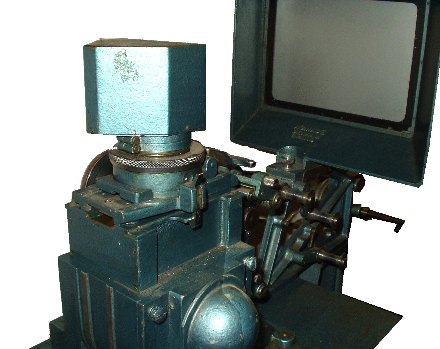
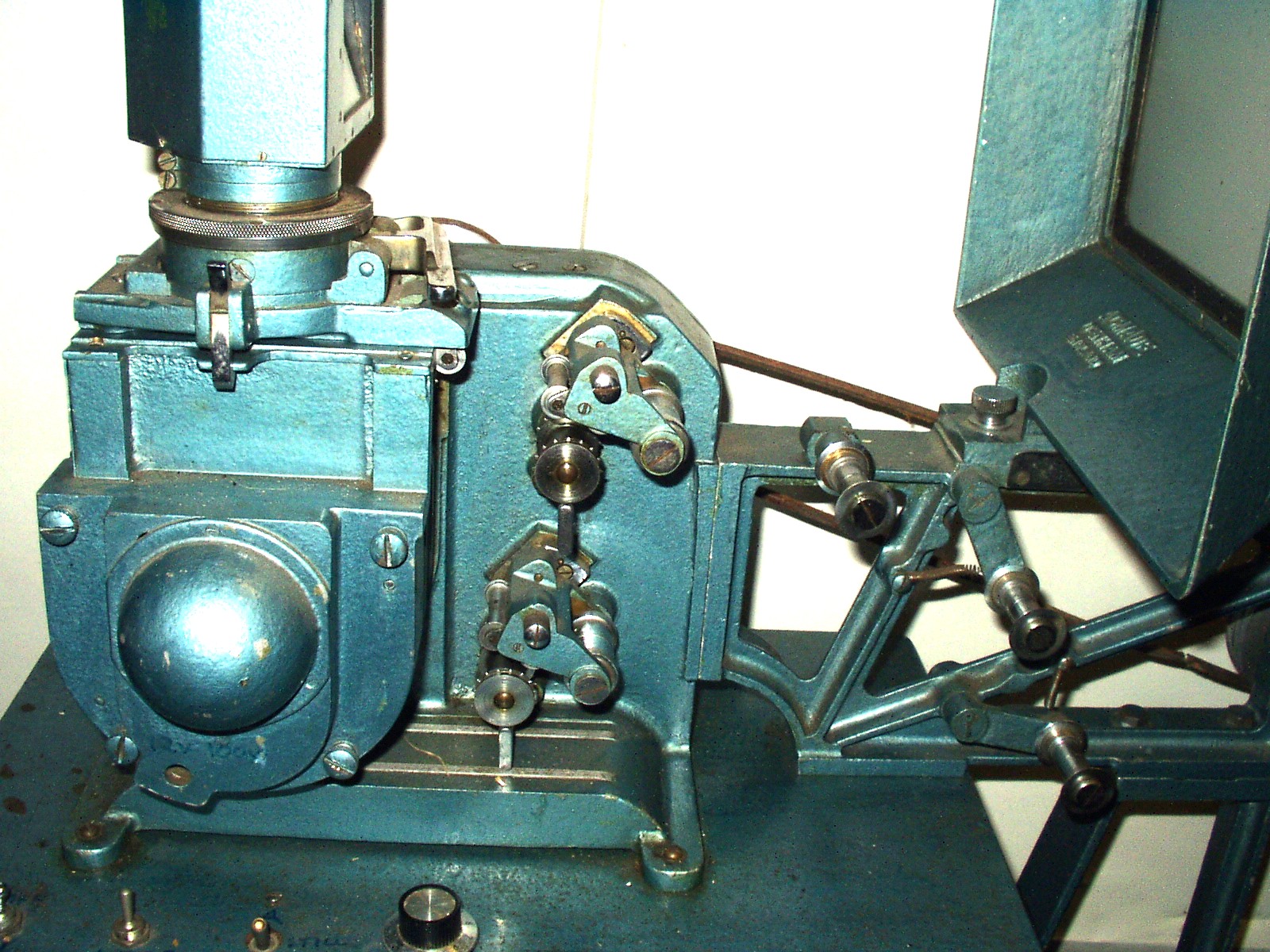
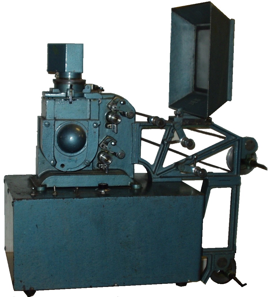
Now here's something I would bet good money that few of you have ever seen. Quite what it was for I dunno - it's like an Acmiola/Ciniola, but with a prism to project the image onto a screen. The only way I can see it scoring over the others is that (I think) it had a shutter.
Please note this next group of pix enlarge one at a time and should be dismissed using the "back" key at the top left of the screen.
Below are a couple of older machines.


A lovely-looking semi-toy 35, a Butcher-Houghton Empire A, courtesy of Trevor Adams in NZ. I assume it is the one in the pic in the ad, but the ad is not clear enough. The Kinox blurb is notable for the poor grammar and the side-swipe at machines that have a dynamo, as well as the insistence on absolute safety. Could both of these last two be references to the KOK? As indeed could be references to enclosed gears. The Kinox pix are a machine I partially restored and ultimately sold. I got it from Steve Siddaway lierally decades ago, and it came with no shutter, no lamphouse or condenser and arms that just slid about in the case. I also had to add a power supply and a "stripper" as I call it, a device for stopping film catching on sprockets when you don't want them to. The lamphouse is, I hope, reasonably professional-looking; aficionados will note a generic likeness to the Pathé Baby lamphouse. The lid survived less well than the machine (by doing its job, I suppose, and protecting the machine), but I have been reluctant to over-paint even the very faded name. Now sold.
Don Sykes sent me envy-inducing pix of his Kinox, with superb transfers still intact.


David Richardson came up with some fascinating stuff on old Empires.

----------------------------------------------------------------------
These are a Pathé mech and 3 shots of a Monopol mech from 1914.


This is a pretty modern cinema machine, a Meopta with trendy, up-to-date red-light sound reading. Except it now seems that, like all the rest, it will soon be confined to museums.
--------------------------------------------------------------
Milinia Eden sent these pix of various 35mm mechs, including a Powers Cameragraph No. 5


--------------------------------------------------------------
Thanks to Pete Diggle, who has sent in this pic of an early (1917-ish) 35mm and some pages from what looks to be a fascinating book.


-------------------------------------------------------------------
A beyootiful Powers 35mm machine spotted by Chris Bird in Nov 2013.


---------------------------------------------------------------------------
Projectors at Auction from a Christies sale. 1. Projection mechanism
35mm., metal-body, with hand-crank and shutter; 2.Reliance Animatograph 1904 model
R. W. Paul, 68 High Holborn, London; 35mm., powder-coated cast iron, brass fittings, hand-cranked projection mechanism, Paul intermittent movement. 3.Empire No. 1 projection mechanism
W. Butcher & Sons, Farringdon Avenue, London; 35mm., black painted cast iron chassis, lacquered brass flywheel and sprocket drums, beater movement, top spool arm, lacks bottom spool arm 4. Empire No. 2 Maltese Cross projection mechanism
W. Butcher & Sons, Farringdon Avenue, London; 35mm., black painted cast iron chassis with brass mechanical components, maltese cross movement, electric light lamphouse and bulb, top and bottom spool arms, 4 inch projection lens 5. Empire Cinematograph model A. W. Butcher and Sons Ltd., London; 35mm., cast iron base with nickel plated brass fittings, maker's plate, external single-bladed shutter, intermittent movement, hand-cranked mechanism, 3 inch lens, electric lamp, black painted metal lid, cylinder form resistance
 6.Projection mechanism Wescoscope; 35mm., cast iron and brass projection mechanism mounted on mahogany base, hand-cranked beater movement, electrically illuminated, lower spool arm, battery holder, pilot lamp, brass bound lens. The Wescoscope is not referred to in the Ariel Register or other specialist literature
 7. Kinox Projector. Krupp-Ernemann, Dresden; 35mm., black-painted metal casting on wooden base with black-painted metal arched lid, gate stamped no. 904090, hand-cranked mechanism with double claw action, electric lamp, an Ernemann Werke Pro-anastigmat 6cm. lens no. 87866. I've got one of these somewhere.
 8. The Ruby projector no. 270. Thornton-Pickard Mfg. Co. Ltd., Altrincham, England; 16mm., cast alloy body with black crackle finish, external enclosed shutter positioned after the lens, mechanism driven by external electric motor stamped NORTH EAST ELECTRIC CO., ROCHESTER N.Y., electric light, the manufacturer's fitted case housing a resistance with variable speed control and compartment with two spools, film rewinding by hand crank, a Dallmeyer f/1.9 2 inch projection lens no. 122078.
9. PLUS model C projector no. 2825
Paris-London Universal-Studios; 16mm., suitcase-style projector, claw movement, electrically driven motor with resistance, black, red and gold illustrated makers label and instructions for use pasted to the inside of the case, a Dallmeyer 2 inch projection lens no. 295198. The P.L.U.S. is not referred to in the Ariel Register or other specialist literature. 10. NS Perforating machine
Newman & Sinclair, London; 35mm., lacquered brass fittings on a cast iron base with maker's plate PATENT NO. 23958 11. 22mm. and 17.5mm. equipment. Usines Gallus, Courbevoie; Cinloc 22mm. projector, black-painted alloy body on steel cone-shaped stand, one 22mm. spool, electrically powered, a Faliez Foyer Siamor 40mm. projection lens; a PathFres 17.5mm. motocamera no. R00935, spring-wound, with a Krauss Trianar f/3 2.5cm. lens no. 276472. http://www.xs4all.nl/~wichm/filmsize.html#OTHER.
Ariel (1981), Cinematographica Register, no. 1034
The Cinloc projector is not mentioned in the Ariel Register. 22mm. Ozaphan cellophane film was produced in 1922 with a conventional layout of a row of peforations each side of the image. It seems to have had a very short-lived existence. The gauge differs considerably from Edison's 22mm. Home Kinetoscope film, which positioned three strips of images and two central perforations across its width.
The 17.5mm. gauge, also with two rows of perforations at the edges of the film, was launched by Pathé in 1926 and achieved only limited success.
- Details
- Category: 35mm
KÖDERS 35mm projector
February 2022
I have been undertaking a task which I could not resist. I acquired, sight unseen, a 35mm “portable” (it feels like it weighs 0.5 tonnes or 'arf a ton as we used to say) projector, a Koders (acherly, it is in caps and hav an umlaut - Ö - but plain Koders is simpler for me). It rapidly transpired that what I would be undertaking was little less than rescuing a projector on the brink of oblivion. It has obviously been stored in the damp at some point, maybe even dripped on a little, and the result was pretty dire, as the main frame and body of the machine was aluminium alloy and so prone to the white “rust” that destroys any surface finish. The side cover and key components such as the sprockets and sound drum were steel. The former’s paint finish (some form of metallic hammered finish) was lifting and flaking across almost its entire surface, inside and out, with the extensive length of vents on each end panel suffering particularly from the rust which covered most of the entire side cover. The paint held on with any tenacity only in odd patches where paradoxically the rust underneath actually improved adhesion.
The sprockets, sound drum, pulleys etc are steel which has been chemically blackened. While offering some protection against rust, this is by no means perfect. There were multiple areas of “spotting”, where rust had pitted the steel. Fortunately, little of this was in key areas, but cosmetically it’s never going to be better than second rate. Not least because the front plate of the machine, a solid piece of alu alloy, is much affected by the white rust and, short of a complete dismantle and repaint and rebuild, it’s never going to amount to much. Possibly the worst of all the problems was the gate runners. These are two vertical strips of a Paxolin-type material, housed in slots and sprung to form the front part of the gate. Unfortunately, the slots are alu alloy and the runners were jammed solid, which took a bit of fixing.
There is also a cover (with a pair of what I have to call very lightweight handles given what they do) that fixes to the baseboard of the projector via luggage-style catches. In my view, only the fact that the catches on the baseboard actually continued round the edge of the board with extra fixings underneath allowed those handles to pick up the projector at all. Although superficially it was not immediately obvious, the catches turned out to be pretty much destroyed by rust. Worse, this extended thru the fixings and on into the wood - the securing bolts were just little bars of rust with no apparent threads and I still ent got them all out. They have left the wood of the cover rather rotted. The wrap-round catches seem to be non-standard as I can't find them on the internet, and anyway the weakening of the wood is going to mean I shall need a pretty ingenious and non-standard solution.
You might by now be wondering why on earth I am bothering. The answer, basically, is that I love messing about with projectors and hate to see a machine like this so neglected. Partly I have always wondered why it seemed necessary for 35mm machines, even so-called portables like the GBN, to be so massive. Obviously, endurance and durability for commercial use, but even so. This machine is the closest I have seen to a 35mm machine that is more or less exactly like the sort of standard layout for a narrow-gauge machine – sprockets above and below and in front of the gate, sound drum below the lamphouse and only a few extra bits to allow for the intermittent sprocket, plus very conventional spool arms. This simplicity does not however do much to make this anything but a bit of a heavyweight.


These pix give you a sort of tour of the machine. In pic 1 I had already started dismantling. The bosses above and below the lens support the shafts for the sprockets. The spool arms fit over the black bosses top and bottom at the front. The two knobs at the rear are (top) the inching knob and (bottom) framing. The lump under the framing knob we will come to in a bit. The gate is open, the runners are still fixed solid. The cap for the sound drum is off, allowing us to see the unusual red PEC. It is at edges and corners that the damage to the paint finish is most visible, but none of it is terribly good.
Moving on, pic 2 starts to reveal the basic construction of the machine, with a thick upright plate carrying the mechanism, supported by a heavily-built framework carrying the motor and amp. This framework was painted all over like the front plate. To me, this seems pointless and little of it was any good, except for gradually spalling off and making a mess. I scraped most of it off with little difficulty. A monitor speaker seems pretty useless against the clatter of a 35mm machine, but nonetheless there is one; just to the right and below is a socket for an external speaker. Note the take-up belt is solid rubber (none of yer spring belts here!), given its grip purely by the weight of the arm and film. This leaves the slipping clutch at the end of the spool arm to provide all the necessary slippage, which on many narrow gauge machines is assisted or entirely dealt with by the spring belt.
In pic 3 can be seen the huge fibre gears for the sprockets, driven by what seems a tiny gear on the inching knob cum main drive shaft. The intermittent box, pretty much central in this pic, has its own flywheel and a drip tray below because it is directly above part of the amp(!?). This drip tray caused me untold trouble when I was re-fitting the sound drum because it was rubbing on the main flywheel. Having settled it in my own mind that the problem was to do with the way the positioning of the flywheel was adjusted (true, but not in the way I was thinking) it took me a while to realise what the problem actually was. The motor wouldn't work when I first powered it up, but when I got it turning fast enough by hand, it fired up, pointing the finger at the start capacitor, hanging loose here. A new one soon sorted it.
Moving on to pic 4, you can see the obvious crack in the base of the capacitor, which had leaked, so not surprising it wasn't working. This machine runs on 115 - 125 volts. The input is via a Bell and Howell plug. Now, I always have problems getting my head around these connectors because of that blasted duplication between two of the pins. This doesn't have that and I worry it might be a problem if some one just plugged an ordinary B&H connector in and iot didn't match the current wiring (I'm not sure it's original), so I shall probably repace it with a 3-pin receptacle of some kind.To the right of the input is the lump seen in pic 1. It is a multi-position switch which goes from (I think) power on to things like the amp and framing light, then motor on, lamp preheat then finally de woiks. This all seems a bit complicated to me, as I would prefer toggle switches like the one just right of the rotary control which is for the exciter lamp. However, this rotary thing seems to do the job so I'll prolly leave it. If you look closely, you can also just see where the sound flywheel and the verdammten drip tray intersect.
Pic 5 is a bird's eye view for completeness. Pix 6 and 7, however, show the underlying horrors of what damp and neglect have done. The plate at the top of pic 6 is the cover for the hole that gives access to the underside of the amp, which I have tucked into a remaining scrap of covering fabric just to show it for the record, so to speak. It seems a weird way to gain (partial) access, at the cost of having to tip up the very heavy machine. Incidentally, once the amp is out, it won't stand up straight because those caps on the tranny at the top of the amp protrude below everything else. There is little sign of rubber feet or similar protection, if there ever were any. You can however see the wraparound catches for the cover. 7 is a glorious Technicolor image of the amp, only closer up. Actually, the amp seems to be in pretty good condition. Except it doesn't work.


Just a few extra pix at this stage. The first two show there were limits to how far I was prepared to dismantle for a machine that would be utiltarian at best, tho' I did remove and clean some of the bits you see here. Note in particular the brass parts - brass don't much like paint and here had rejected it more or less completely - I just tidied up. Pic 3 is the worst example by some way of rust to the blackened steel parts. But it is the main drive pulley! 4 shows the mess rust made of the latches, catches and of the cover - I just don't think it would be safe to use the same holes without reinforcement, but note the wrapround on the catch part.
I ent yet showed you the outer cover or the inner mech side cover.


The outside looked quite respectable at first, until you looked at the latches. Note the cut-out of the base front left, which the cover extends into. This makes room for the take-up reel. The inside was difficult to photgraph as it's all terribly red and my poor little camera didn't know where to focus. There was a lot of discolourisation and white mould-like powder, quite apart from the internal "anchor" pieces for the handles, which have almost completely rotted away. And the felt lining had come loose and was ready to go further.
Pic 3 shows the inside of the mech side cover. This shot is after a lot of work removing not so much the flaking paint as the more stubborn bits that had managed to stay stuck on and sanding away the worst of the rust. The area along the top of the rear of the cover (about two thirds of the way up this pic) was heavily covered by thick layers of paint both inside and out, under which was a lot of filler with, underneath that, the rust you see here. I am a believer in getting to the root of rust rather than covering it with another coat of paint, so did more work and applied rust killer. Ironic that it was the rust creating the adhesion of the paint in this area. It appears to be some sort of butt-weld; I have no idea why as such a curve would seem no problem at all for steel of this fairly thin section. Maybe the sides and top are a single piece, with the specialised pressing for the vents all on the one piece? Pic 4 shows the vents which are as usual very difficult to work on - I had quite a bit more to do after this pic was taken. Pic 5 is a detail of that join seen in pic 3.


I suppose you could call this batch of pix "after" pix, although I have done little with the paint on the main plate of the mechanism.I have however had a go at painting the side cover with silver grey Hammerite. Far from perfect - it's just too big for my small workspace - but at least it will look better, runs notwithstanding, than it did when I started and won't rust for a while. I now need to clean up the top cover, re-cover the base and devise a solution to the fixings and appearance issues. Then there is the amp, tho I may cheat and just use a diode fed to an external amp, tho the exciter lamp feed seems to come from the amp tranny. So, plenty more to do yet, but now it runs and has light. It also has that typical 35mm clatter - no wonder they usually got shut up in a boof.
I have explained my problem about the catches that both held the lid on and supported the entire, very considerable, weight of the projector. I cannot find any catches which do the job in a way I consider safe, particularly repeating the wrap-round under the base from the original. I needed to put the new arrangement in the same place as the old catches because the mess left under them is so extensive I wanted something to both cover it and add strength. I have therefore come up with my own, multi-part solution.
First, a piece of aluminium angle about 70mm wide and with the angled sides about 0.5” (edge of baseboard) and 1.5” (underneath baseboard) is screwed to the baseboard from underneath. The short edge is screwed to the side of the baseboard, but with screws first passing through one half of a substantial hinge that (and this is the key to the entire approach) has a removable pin.
The other half of the hinge is fixed to the cover, with bolts passing thru first the hinge, then an aluminium plate about 70mm square, then the cover itself, then another aluminium plate (70mm square again) and finally secured by washers and nuts. Two further bolts in the upper portion of the aluminium plates complete the fixings.
All of this is of course much simpler to see with a couple of photos; here they are.


The first pic is from underneath the baseboard, showing the wrap-round I consider essential - can't expect a few screws into the thin edge of a piece of plywood to do the job on their own. I managed finally to get a decent shot of the inside of the cover. I shall need to do some trimming of the bolts to prevent scratching the machine (even more).
I can’t claim the result is as good as the original, as the lower part of the hinge protrudes above the edge of the baseboard but, even if I could find direct replacements, I don’t think they would work without the strengthening I have incorporated. In fact, I am beginning to wonder if I might have been better off making an entirely new base.
Then there is the question of feet. The bottom of the baseboard appears to have been covered with the same material as the sides and top, but with use and damp it was loose and useless, what there was left. I can’t really tell if there were ever feet but, if there were, they are long gone. Leaving a flat surface that would inevitably be abraded (and abrasive) seemed ineligible so, after much pondering, I fitted 6 Teflon gliders, supporting the baseboard at the three main corners and at the three “corners” of the cut-out. Once I had the machine set up, it became apparent just how badly the baseboard had been weakened, as it sagged almost to the platform it was on between the two rear feet. I shall probably have to reinforce.
Some Time Later.......
I have been struggling to commission this verdammten machine, but it has continued to place obstacles in my way. Let me deal first with the amplifier. I got it working with an external input to the mike socket, and it gives a really good, clear result. So far so good. I installed a diode in place of the PEC, and the problems started. There was insufficient volume, tho’ I could tell something was there. So I dug out a pre-amp, made many years ago. Since then, I have had nothing but spits, crackles, tearing noises – the usual gamut – and, before you point out the obvious, this has now retroactively affected the external input – without the pre-amp. I also get complete loss of sound, very patchily, involving much fiddling with the jack input to try to get it right – and failing for any serious length of time. More work required here, obviously.
Another thing that happened was when I re-wired the lamp (I’ll explain why in a bit). My increasing clumsiness helped me to break the lampholder and socket, tho’ spares were of course lying around in my lampholders box and the lamp attic.
Even more aggravating has been the behaviour of the film transport mech. This has basically involved two problems. The first is longitudinal splits in the film, anything from just the sprockets to halfway across the frame – and 35mm don’t ‘arf get thru a lot of film in the time it takes to notice, panic, then act. Fortunately, I am only using an aged batch of trailers, but all that splicing and re-threading takes up time. As does finding the 35mm rewind arms, which I didn’t think I would ever need and had put away somewhere, and their baseboard, making extra holes and re-positioning the arms (don’t ask), so that I can start again without scarring a new piece of film. And dismantling and sorting the splicer, which was obviously in dire need of both blade and punch being sharpened. I think one of the defining features of using old cine equipment is the constant need for maintenance and repair and the requirement for a large range of equipment and tools and spares to help. And if you ent used it for a while, few projectors will forgive you easily.
But I digress. The second problem is the film just snapping, initially because the take-up needs help to start, and snatches when it catches up. This is not too difficult to deal with, but becomes much tougher when it keeps happening because the main projector control is rotary and every step in the sequence involves a break in power supply, eg after “motor on” there is a disconnect before “motor plus lamp pre-heat” and another between that and “lamp full on”. These stops re-prime, so to speak, the need for help to the take-up. Now we have all started narrow gauge films with slack in the take-up and just let it catch up, but 35mm does not like this because everything moves too damned fast, and the film breaks. Most recently, the film broke when I stopped the machine with film still running. I have adjusted both the take-up and the feed tension to help deal with this.
Now, I have often suspected that the rotary control on the machine when I got it was not original, and the realisation of the breaks in the power supply tended to reinforce this view. So I decided to re-wire with switches, which is more what I am used to. After much lucubration (I have no idea where I got this word from but I think it just means thought), I came up with:-
a) a double-throw motor switch with centre off, up being motor only and down power to both motor and lamp switch. This is to enable the motor to be run eg for cooling without the pre-heat on.
b) a double-throw lamp switch with only two positions, up being pre-heat and down full power; the lamp pre-heat therefore comes on when the motor starts. I am assuming it don’t need long in pre-heat.
c) separate switching for the amp and the exciter. In effect, the amp switch allows power to the valve heating circuits, the separate on-off switch on the amp volume controlling the rest of the amp. The exciter has its own switch although the supply is actually from the amp – I am not actually sure where in this chain of switches the exciter falls. A pilot lamp circuit relies on its own switch direct from the power inlet.
All this required quite a bit of re-wiring, in the course of which I busted the lampholder and the pins of the lamp itself, which seem to be more sensitive to being “adjusted” (bent), said adjusting forces resulting from a failed attempt to repair part of the lampholder with superglue, which rarely seems to work for me. Another part of the re-wiring was to swap the inputs. As received, all the switching was on the negative side and I felt uncomfortable with this.
The machine arrived with the old-style 4-pin-plus-location-pin B&H 110v plug and socket, but wired for 3 wire input. I always felt dubious about this – what if someone plugged a differently-wired plug in? Might one get a live chassis? So I swapped it for a C19 and C20 IEC pair – these look like a slightly larger version of the usual C13/C14 pair of the standard kettle lead, but with the pins horizontal rather than vertical. No-one is likely to stick the wrong lead into that, as they seem difficult to find. You can see the new electrical set-up below.

- Details
- Category: 35mm
35MM PROJECTORS
This page shows various pictures and bits and pieces I have accumulated about 35mm. In a few cases, so far the
EDUCATOR, the COSMOGRAPH and the KÖDERS I have enough to justify a separate page.
Debrie
This is a 1920s "Jacky" Debrie, a 35mm machine not unlike some of the cameras Debrie were producing at the time. Until the prospect of taking it to Argenteuil in 2020, I had not even taken it out, let alone fixed and tested it, despite having had it for several years.
Here are some pix; these are mostly stolen from the internet, but my machine is exactly the same, except I do not got the spool-box things. The only pix that are mine are the switch mech. While I was re-doing the photos for this page I came across a pic from one of my visits to Argenteuil so I have just tacked it on the end.
It's a very strange machine. The strangest bit is that the film has to cross over by 3 or 4 inches to reach the bottom sprocket. The machine was pretty seized up when I got it, and I spent many days coaxing it back to life. A particular problem was the switch mech, which I had to take apart quite a bit as it was integral with the double motor resiatance, both parts of which had cracked clean in two, fortunately without breaking the wires. I super-glued them together then used epoxy putty to reinforce the repair and keep the wires around the break area firmly in place. Figuring out how to connect it all back up again once I'd done the repair took me quite while.
My machine is avialable to buy to anyone who can fork out £1k or suggest a sensible offer.
This first picture is a bit old, dating back to 1997, in an issue of Image Technology. This is the Journal of the BKSTS (British Kinematograph, Sound and Television Society). Putting three digital sound systems on the same film with the analogue track was then seen as simply a technical possibility, possible because all three used different areas of the film.
The analogue track has come a long way from the early days of mono sound tracks, with twin tracks for stereo and companies like Dolby squeezing surround sound and other effects from it. The DTS system, as I understand it, simply provides a time code to a sound unit playing the equivalent of a CD. This has the advantage that you just change the CD to change the language the audience hear. Film breaks don't matter as the coded signal simply shifts the CD on to the correct place. The Dolby SRD system I find particularly fascinating, as it breaks away completely from the linear, analogue approach, by placing the digital soundtrack information in separate "packets" between the sprocket holes. This really exploits the possibilities of digital, allowing discontinuous info to be processed to create a continuous soundtrack. I once attended a talk by a Dolby engineer, who said that they had found that the inter-sprocket area was very little affected by wear, except right in the centre of the "packet". So they didn't use that bit for soundtrack info, but put the Dolby double-D logo there instead. Now that I call inspired, tho' I don't know if they still do it. I don't know anything about the SDDS system, tho' it looks like digital info in a conventional linear form. More about the evolution of Dlby sound is in this pdf. DOLBYEVOLUTION.pdf
This is a drawing I found (probably from BKSTS again) with the dimensions of a TODD-AO projection print. I love this sort of detailed stuff. Huge amounts of it, of course, on that series of big posters BKSTS did on film gauges, colour systems etc some years back. I also have a bad copy of an article by Grant Lobban MBKS from the BKSTS, called 35mm Release Print Formats. This dates from 1970 and was 8 then. I don't know where I got it or why anybody bothered copying it, because without top quality pix it's useless, but if you're into this kinda thing, it looks fascinating.
-------------------------------------------------------------------------------------
I always used to wonder why they couldn't make 35mm projectors that were only a bit bigger than 16mm instead of unbelievably heavy and cumbersome. As my projection facility is in the loft and I have too much stuff, size and weight are serious considerations. Eventually I found one; I have seen others, too, so it obviously can be done.
The best that used to be available was the GBN, (pic 1 below), immensely heavy and limited capacity.
Pix 2 & 3 above are a Marin. 3 - 6 are Microcine; the innards are interesting - everything is driven by toothed belts. The fans for cooling the Xenon lamp and its power supply (which is integral) are just standard 80mm mains-operated computer case fans. (See the Microcine website; link in Miscellany). Pic 7 is from Argenteil; very like the Microcine it is clearly designed for backroom/technical/laboratory use.
I found the first three pix on eBay. The machine is called a Kinelite - from the back view it seems to be a fairly stripped-down machine - but still pretty compact. Couple more for you, an Oxford and an unidentified. The Oxford has the same basic layout as the DeVry; Pic 5 seems very reminiscent of the Chinese-made Spectra (see below). The last is from Argenteuil.
----------------------------------------------------------------------
The first four are of a Spectra I had at one time. It was a lovely little machine, but marred by that huge power pack/ballast (pic 4) and the fact it took only 2000' spools. With the boxes I suppose it could in principle show nitrate, which might still have been around, in some parts of the world at least.when the Spectra first appeared. The Spectra was a Chinese machine, imported into the UK by some British company. The range included a pair of these, complete with stands, 1000 watt Xenons, a single power supply or "ballast" cum changeover unit (which weighed more than the machine itself - old technology), an amplifier, a pair of rewind arms and a tape splicer. They were aimed at cine clubs and similar. Spool capacity was only 2000ft, so changeover operation was needed, and operators had to have a degree of skill. The same company also imported a full-size theatrical machine and cakestand aimed at small cinema operations - there was one in my local library theatre, I discovered and is now with the PPT (pic 5). I acquired one of a pair of the "portable" type, together with the Xenon power supply, as seen here and the amp. (The other machine, bereft of its power supply, got converted I think). I seem to recall I did have the stand, but didn't use it as I needed all my projectors to be moveable - it's on a wheeled stand in these pix - but not the splicer or rewinds. (Curiously, I did acquire the splicer and rewinds, in a completely separate transaction, a year or two later; the splicer was an obvious rip-off of the CIR. I later had it converted to 28mm. The rewinds, bench-edge-mounting type, are still around).
The critical problem for me was the 2000ft limitation, making running anything longer than two reels a chore, so in the end it had to go to be replaced by the Microcine above. However, it was a beaut bit of kit, good old-style engineering and few belts. It did leak oil from the intermittent gearbox tho'. I have seen variants on it at Argenteuil (last 2 pics above). They show the ugly arrangement needed to get more than 2000'.
Above are some leaflets I found at Argenteuil, proving 35mm machines do not need to be huge and requiring a crane.
Dino Everett spotted a fascinating machine on ebay - an obvious clone of the 28mm Premier Pathescope - or vice versa. Dino tends to the view the 35mm came first, a notion which seems logical and is supported by the wonderfully primitive motor, with a very useful inching knob. But very few other changes apart from the obvious and the name plate. I must admit I have always wondered how on earth Willard Beech Cooke came up with an excellent 28mm projector from thin air, and this must surely be the answer - he didn't, he just copied an existing 35mm machine.
There is a shaft at the back, absent from my 28mm version, which may have been for an external motor, or an output to ...... what? The friction brake present on my 28 is missing, tho' there may be a hole where it fits...... The most difficult feature to reconcile is that tiny two-bladed shutter. Is it original? I can't see how anything that small could do the job, and a two-bladed one would maybe need to rotate faster anyway, which would require changing gear ratios, which could be tricky. I assume it is a purely cosmetic addition for display purposes by a sometime owner. So it appears Cooke simply copied the 35mm machine - not much more than badge engineering - and bought in a batch of surplus sewing machine motors (mine literally states that on its maker's plate) for the drive, to overcome the shortcomings of the KOK and, no doubt, to cope with lack of supplies of the KOK from a France at war. I wonder if there is any link to the Peerless company that made the early Triplico-type machine and the SP Wundatone?
My 35mm Ciniola, long since departed.
Now here's something I would bet good money that few of you have ever seen. Quite what it was for I dunno - it's like an Acmiola/Ciniola, but with a prism to project the image onto a screen. The only way I can see it scoring over the others is that (I think) it had a shutter.
Please note these pix enlarge one at a time and should be dismissed using the "back" key at the top left of the screen.
Below are a couple of older machines.
A lovely-looking semi-toy 35, a Butcher-Houghton Empire A, courtesy of Trevor Adams in NZ. I assume it is the one in the pic in the ad, but the ad is not clear enough. The Kinox blurbis notable for the poor grammar and the side-swipe at machines that have a dynamo, as well as the insistence on absolute safety. Could both of these last two be references to the KOK? As indeed could be references to enclosed gears. The Kinox pix are a machine I partially restored and ultimately sold. I got it from Steve Siddaway lierally decades ago, and it came with no shutter, no lamphouse or condenser and arms that just slid about in the case. I also had to add a power supply and a "stripper" as I call it, a device for stopping film catching on sprockets when you don't want them to. The lamphouse is, I hope, reasonably professional-looking; aficionados will note a generic likeness to the Pathé Baby lamphouse. The lid survived less well than the machine (by doing its job, I suppose, and protecting the machine), but I have been reluctant to over-paint even the very faded name.
David Richardson came up with some fascinating stuff on old Empires.
Don Sykes sent me envy-inducing pix of his Kinox, with superb transfers still intact.
----------------------------------------------------------------------
These are a Pathé mech and 3 shots of a Monopol mech from 1914.
This is a pretty modern cinema machine, a Meopta with trendy, up-to-date red-light sound reading. Except it now seems that, like all the rest, it will soon be confined to museums.
I suppose as this is called a professional I have to put it in 35, not toys.
--------------------------------------------------------------
Milinia Eden ent these pix of various 35mm mechs, including a Powers Cameragraph No. 5
--------------------------------------------------------------
Thanks to Pete Diggle, who has sent in this pic of an early (1917ish) 35mm and some pages from what looks to be a fascinating book.
-------------------------------------------------------------------
A beyootiful Powers 35mm machine spotted by Chris Bird in Nov 2013.
---------------------------------------------------------------------------
Projectors at Auction from a Christies sale.
1. Projection mechanism
35mm., metal-body, with hand-crank and shutter;
2.Reliance Animatograph 1904 model
R. W. Paul, 68 High Holborn, London; 35mm., powder-coated cast iron, brass fittings, hand-cranked projection mechanism, Paul intermittent movement.
3.Empire No. 1 projection mechanism
W. Butcher & Sons, Farringdon Avenue, London; 35mm., black painted cast iron chassis, lacquered brass flywheel and sprocket drums, beater movement, top spool arm, lacks bottom spool arm
4. Empire No. 2 Maltese Cross projection mechanism
W. Butcher & Sons, Farringdon Avenue, London; 35mm., black painted cast iron chassis with brass mechanical components, maltese cross movement, electric light lamphouse and bulb, top and bottom spool arms, 4 inch projection lens
5. Empire Cinematograph model A. W. Butcher and Sons Ltd., London; 35mm., cast iron base with nickel plated brass fittings, maker's plate, external single-bladed shutter, intermittent movement, hand-cranked mechanism, 3 inch lens, electric lamp, black painted metal lid, cylinder form resistance
6.Projection mechanism Wescoscope; 35mm., cast iron and brass projection mechanism mounted on mahogany base, hand-cranked beater movement, electrically illuminated, lower spool arm, battery holder, pilot lamp, brass bound lens. The Wescoscope is not referred to in the Ariel Register or other specialist literature
7. Kinox Projector. Krupp-Ernemann, Dresden; 35mm., black-painted metal casting on wooden base with black-painted metal arched lid, gate stamped no. 904090, hand-cranked mechanism with double claw action, electric lamp, an Ernemann Werke Pro-anastigmat 6cm. lens no. 87866. I've got one of these somewhere.
8. The Ruby projector no. 270. Thornton-Pickard Mfg. Co. Ltd., Altrincham, England; 16mm., cast alloy body with black crackle finish, external enclosed shutter positioned after the lens, mechanism driven by external electric motor stamped NORTH EAST ELECTRIC CO., ROCHESTER N.Y., electric light, the manufacturer's fitted case housing a resistance with variable speed control and compartment with two spools, film rewinding by hand crank, a Dallmeyer f/1.9 2 inch projection lens no. 122078.
9. PLUS model C projector no. 2825
Paris-London Universal-Studios; 16mm., suitcase-style projector, claw movement, electrically driven motor with resistance, black, red and gold illustrated makers label and instructions for use pasted to the inside of the case, a Dallmeyer 2 inch projection lens no. 295198. The P.L.U.S. is not referred to in the Ariel Register or other specialist literature.
10. NS Perforating machine
Newman & Sinclair, London; 35mm., lacquered brass fittings on a cast iron base with maker's plate PATENT NO. 23958
11. 22mm. and 17.5mm. equipment. Usines Gallus, Courbevoie; Cinloc 22mm. projector, black-painted alloy body on steel cone-shaped stand, one 22mm. spool, electrically powered, a Faliez Foyer Siamor 40mm. projection lens; a PathFres 17.5mm. motocamera no. R00935, spring-wound, with a Krauss Trianar f/3 2.5cm. lens no. 276472. http://www.xs4all.nl/~wichm/filmsize.html#OTHER.
Ariel (1981), Cinematographica Register, no. 1034
The Cinloc projector is not mentioned in the Ariel Register. 22mm. Ozaphan cellophane film was produced in 1922 with a conventional layout of a row of peforations each side of the image. It seems to have had a very short-lived existence. The gauge differs considerably from Edison's 22mm. Home Kinetoscope film, which positioned three strips of images and two central perforations across its width.
The 17.5mm. gauge, also with two rows of perforations at the edges of the film, was launched by Pathé in 1926 and achieved only limited success.
- Details
- Category: 35mm
Educator
THE EDUCATOR
The pictures here actually survived the transition to Joomla! and so show up one at a time and must be dismissed by clicking the Back arrow top left of your screen. You try to do it with the X on the right and the whole web connection will go.
The guy selling this on eBay did a first-rate job of photographing and researching this very rare projector, so I'll let him explain it in his own words.
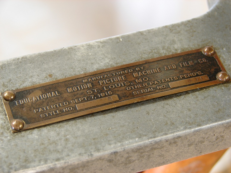
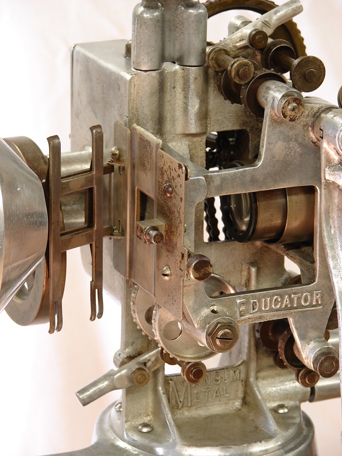
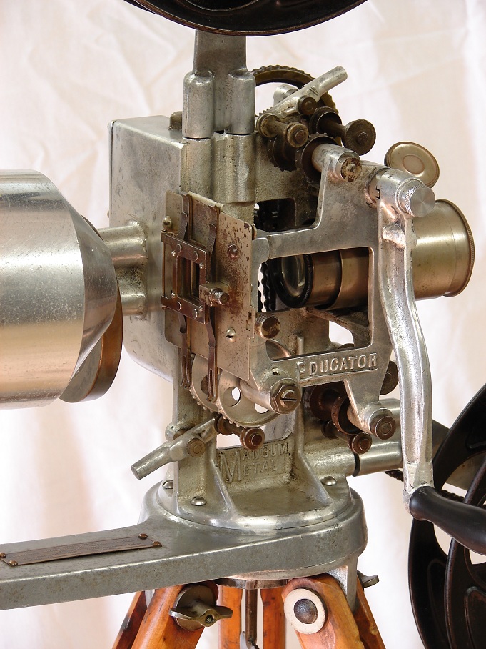
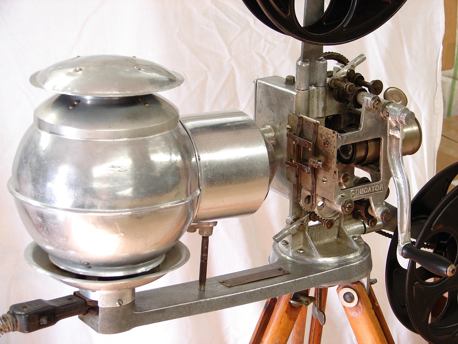
"As 35mm movie projectors go, this is certainly one of the rarest. It is so scarce that many seasoned collectors of cinema equipment are not aware of its existence. It is branded simply as the Educator and was made by the Motion Picture Machine & Film Co. of St. Louis Missouri. Production began with the filing of patents in 1916 and did not last for very long. It is believed that fewer than 500 machines were ever built.
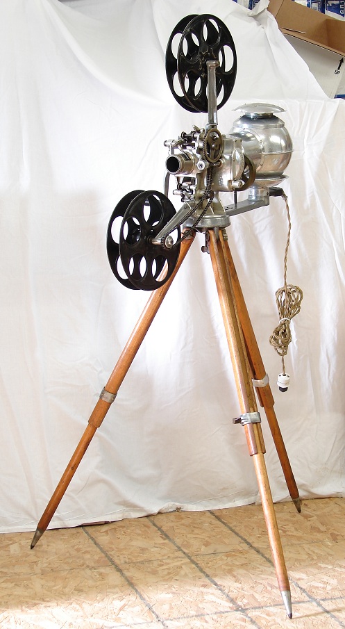
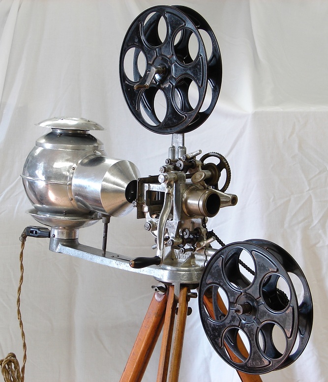
Currently, there are only four examples of this projector known to exist, including this one. Of the four known, this is one of two that is complete and in good condition. Of the other 3 machines, one is missing the original tripod and reel arms, and one has a main casting which is broken into two halves. The projector offered here is totally complete down to the last screw. The original crank handle has two very old weld repairs, and the lamp housing has a few dents in the spun aluminum. Otherwise there are no broken or damaged parts. When I found the projector one of the 3 aluminum and brass leg adjustment clamps were missing. Using one of the two remaining originals as a sample, I had an exact replica fabricated by a professional machinist. I have shown a close-up photo of the replica clamp as well as one of the originals. As you can see, aside from the metal being un-oxidized on the replica, they are totally identical. All other parts are original to the machine.
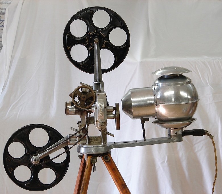
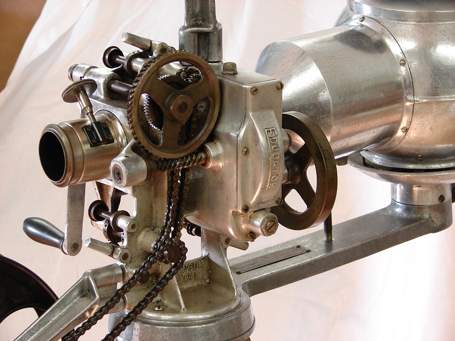
One nice thing about the Educator is its small size. As you see it in the photos, it measures 57" from the top of the upper reel to the floor. From front to back it is 31" and each of the 3 legs are 34" apart where they touch the ground. With such a small footprint it can be comfortably displayed in just about any size room or office. Also, because it is almost entirely made of aluminum, you can easily pick it up and move it around when fully assembled. The appearance of the Educator is very unique. I can honestly say that there are no other 35mm movie projectors that look anything like it. It has a very futuristic and modern look, especially with all of the bare aluminum. It looks more like a prop from a Buck Rogers film than a circa a WWI motion picture machine.
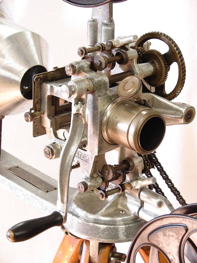
Mechanically, I think that the Educator is best described as bizarre. The first thing that I found odd about it was the absence of a shutter of any sort. At first I thought that the shutter might be missing, but after seeing that none of the other 3 examples had a shutter I realized that it was designed and built without one! Also I was able to find the original patent drawings (which I have a link to below) These show the entire design of the machine and clearly no provisions for a shutter blade were ever made.
CLICK HERE TO SEE THE ORIGINAL 1916 PATENT DRAWINGS.
Another unconventional design feature is the way in which the intermittent movement is driven. The crank shaft is attached directly to a large round gear. When turned, this gear drives a horizontal worm gear which has the intermittent disc and a large flywheel attached to it. By looking at this backwards and very awkward design you would think that the crank handle would be very hard to turn, but surprisingly it is turns very easily and smoothly. The intermittent movement is also very strange. It is a somewhat similar to the drunken screw design and is nothing like the conventional star and cam that was so widely used. A link to the original patent drawings for the intermittent is below. It is well illustrated, showing and explaining in detail how the movement works.
CLICK HERE TO SEE THE ORIGINAL INTERMITTENT PATENT PAPERS.
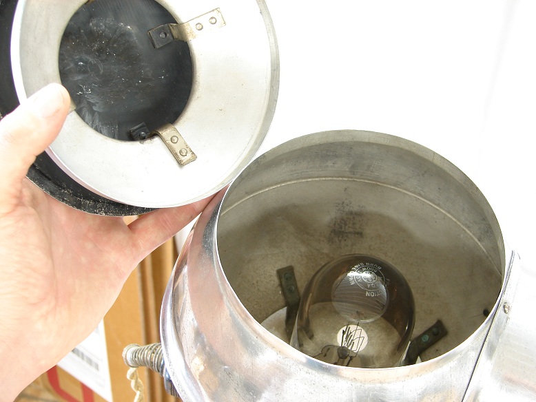
Overall the projector is in excellent condition and looks great. I have carefully cleaned it and it is ready for display. There is some minor rust and oxidation to the metal, but nothing serious. The wood tripod shows normal wear to the original finish. The mechanism turns very smoothly and freely and all parts move and function as they should. The original lens is free from optical defects and focuses smoothly. The cloth insulated electrical cord is in great shape with no fraying. The original white porcelain light socket style electrical plug is intact and excellent shape. Inside of the lamp house is a very old 1000 watt mogul base incandescent projection bulb. It is well used with darkened glass but still working. Also the condenser lenses are in place and in excellent shape with no chips or cracks.
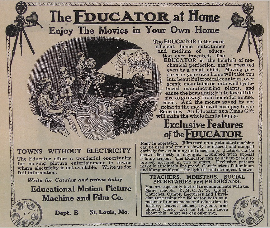
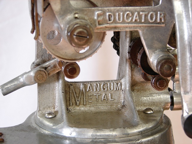
Also included is an enlarged color photo copy of a 1916 magazine advertisement for the Educator. This is the only piece of published literature that I have ever seen for this projector. It is quite entertaining to read. Like pretty much every other manufacturer of their time, they make some pretty outlandish claims regarding the features and abilities of their machine. My personal favorite is their reference to the cast aluminum as Mangum Metal, the lightest and strongest known Also their assertion that Exclusive patents make it absolutely fire proof is hilarious. I suppose they must be referring to the metal parts not being combustible! A wonderful opportunity for Towns Without Electricity is quite an odd statement since the light source is an ELECTRIC BULB. The illustration is pretty funny too, it shows a young boy operating the projector from the side without a crank."