Been playing about with my original Super Rural again and I think have got it working well. This shows the original type of retaining roller for the  hold-back sprocket on a Super Rural, together with my attempt to copy it. The lump of aluminium is a length of bar, extensively shaped and cut about, with a central bore for the long arm with the slot in it. This is needed because someone actually went to the trouble to hack off the original lugs that carried the arm. Go figure. So I have had to try to make a new pair of lugs, and a means of fixing them to the machine. Tricky, as I have very little depth where it goes before hitting the shaft on which the sprocket itself sits. Rendered even more difficult by the fact that, in a masterpiece of design, the entire front arm assembly is one huge piece and at some angles won't fit my machinery.


The first two show how the set-up should look, compared with how the second one actually does look. To call this bodgery of the worst kind is hardly enough. The next two show my restoration effort once completed. Pix 5 and 6 show the replacement cover I made for the horrid abortion that had replaced the original sound reader. Pic 5 also reveals some of the other digusting things done, eg replacing the top sprocket guide with a debrie type with no thought for the possibility other aspects of the SR design made this useless.


Pic 1 above shows the layout of the soundhead area of the machine as I received it. The three small brass rollers are an addition, fixed to a plate located in a slot cut out of the face of the projector. You should be able to see the outline of the plate. You will note also that there is no middle sprocket. The idea of this piece of lunacy was to lengthen the film path in advance of the sound reader because of the issues I have discussed elsewhere over what is the proper length of sound separation as between French and English machines.
Pic 2 shows my first attempts to deal with this and restore the machine a bit. Not only had the third sprocket been removed, but the internal gears had been discarded too! I had new gears made; fortunately, how I know not, a third sprocket had somehow survived. I made a new plate and mounted a pair of rollers pivoted on this. As I received the machine, there was an arrangement of this type, but it had to be changed to accommodate the replaced middle sprocket. You will see the original sprocket retaining roller for the third sprocket had been removed and a plate mounted instead. To complete this little corner of madness, Pic 3 shows what was done to the top sprocket - it's supposed to be like a Debrie and is ingeniously done, but it don't work! This, too, will have to be restored. You will note the sprocket in this pic has holes in the side. All the sprockets on the other machine have a plate fixed here which is 38mm, about 2mm more in diameter than the sprocket, so forming a guide lip to help keep the film on the sprocket. I have made one from scratch, but it's hard work and not terribly satisfactory - you can see it in one of the pictures just above. For the other two, I have some repair washers of a diameter halfway between, ie 37mm or 1.5" which I will adapt.
Another problem is that the Elf amp inside the casing seems to give rather distorted sound, while an external amp gives excellent results. I suppose I shall have to go in and sort it, but it's a lot of fiddling as the main plate to which the amp components are attached has to be cut about to fit, and because of the way everything is wired together, I can only test a replacement amp once more or less fully installed.
When I first wired the machine up several years ago, the only way I could find to achieve a motor/lamp interlock was to make the motor switch control the mains input to the entire machine. So there was no amp until the motor was running, and I didn't really like that. After discussion with a friend, I tried again, wiring one wire of both the 110v for the motor and the 24v for the lamp thru the motor switch together, before going on to the motor and the lamp switch. This gave me interlock OK, but as I am usually good about switching motor off before lamp, I didn't find the problem at once. For reasons that I confess are not clear to me, I now have a 2-way switch sort of arrangement. If I switch on either the lamp OR the motor switch, the motor starts. If I then operate the other switch (either the motor or lamp, depending on which I pushed first), the lamp comes on. Switching off is the same; either switch will turn the lamp off, and the other then turns the motor off. Apart from anything else, this removes the option of one-switch emergency off, the second main point of having an interlock (the first of course being to stop the lamp being on without motor.) I shall have to think again.
I have now sorted this, with much advice from Noel Pratt, by inserting a relay to control the lamp current. Basically, the motor switch is actually switching the mains supply to the motor tranny; once this switch is on, the tranny is fed and in turn feeds the motor. The switch also controls a mains feed to the relay; once the switch is on, the relay allows current to go to the lamp. If the relay is not receiving current, ie the motor switch is off, then the lamp gets no current. I did do a rough diagram which I shall try to include.
In an attempt to deal with the distorted sound problem (I hardly had to move the volume control from 0 to get sound too loud), I have added a potentiometer across the input to the amp, which I can adjust from outside via a small hole. Now working on the lamp, which I think is way out of alignment. I find along the way that the lens housing is the same size as Debrie lenses, but none of the short throw ones I have will go far enough back towards the gate to focus.


First pic shows top sprocket as restored. Seems to work well, tho' have yet to try it with damaged or extensively repaired film. 2nd is the third sprocket. The restored retaining roller is L; R I have taken advantage of the alterations that had previously been done. I have re-shaped the plate that had been fixed behind the sprocket, and used it to provide a sprung smoothing roller for the take-up. I felt the need for this partly because the take-up, gear driven from the centre of the spool arm, is not quite smooth and partly because I think the use of 2000ft reels will need this.
We then have a view into the lamphouse. Originally, this whole side of the lamphouse was solid; as you can see, a large hole was hacked into it, and a crudely-fashioned lamp arrangement inserted. I have not really changed this much, other than to give the lampholder more space for adjustment as it was way out of line, and to re-arrange the wiring so it is possible to change the lampholder without having to undo the wires from the back. The final pic shows the box I fitted to the back of the motor - where there were just bare terminals when I got the machine. Originally, the feed to the exciter lamp also went thru a (much smaller!) box here. Now the feed goes via a socket on the side of the switch housing.
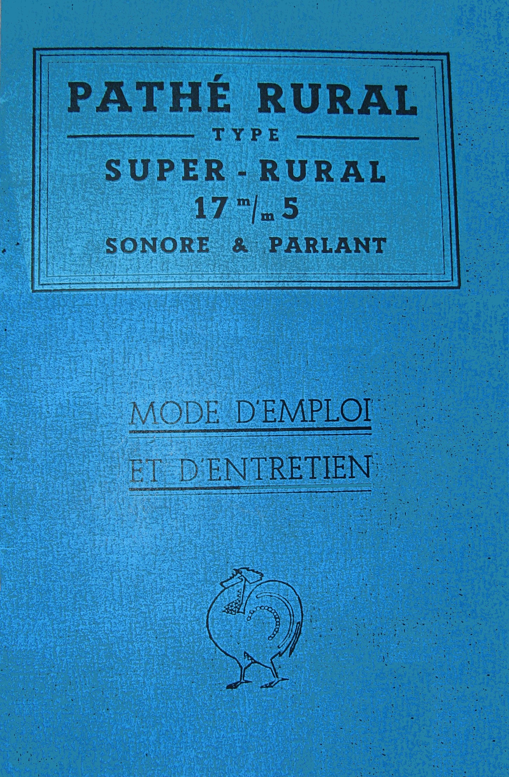
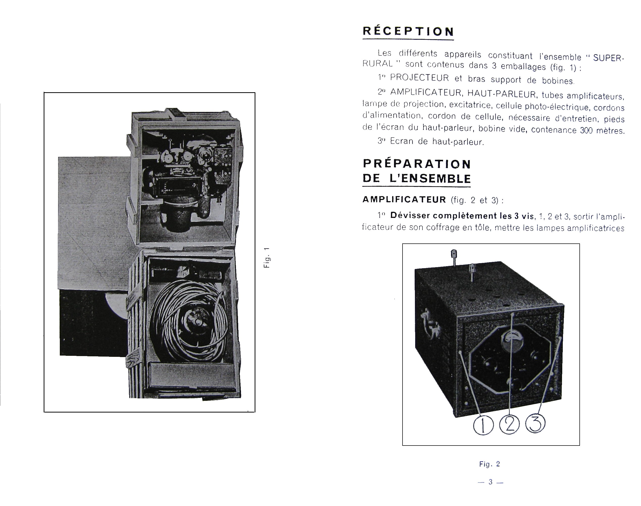
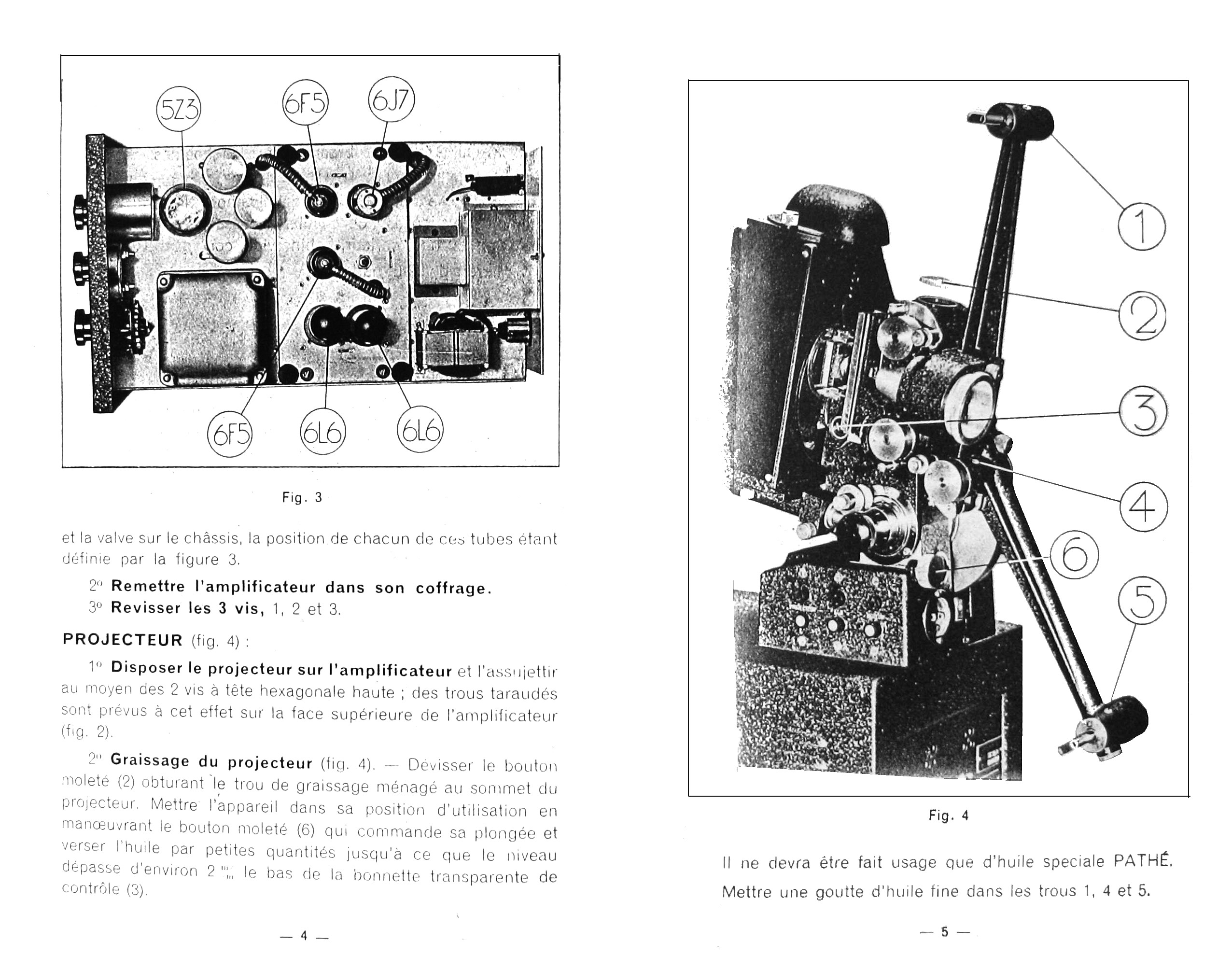
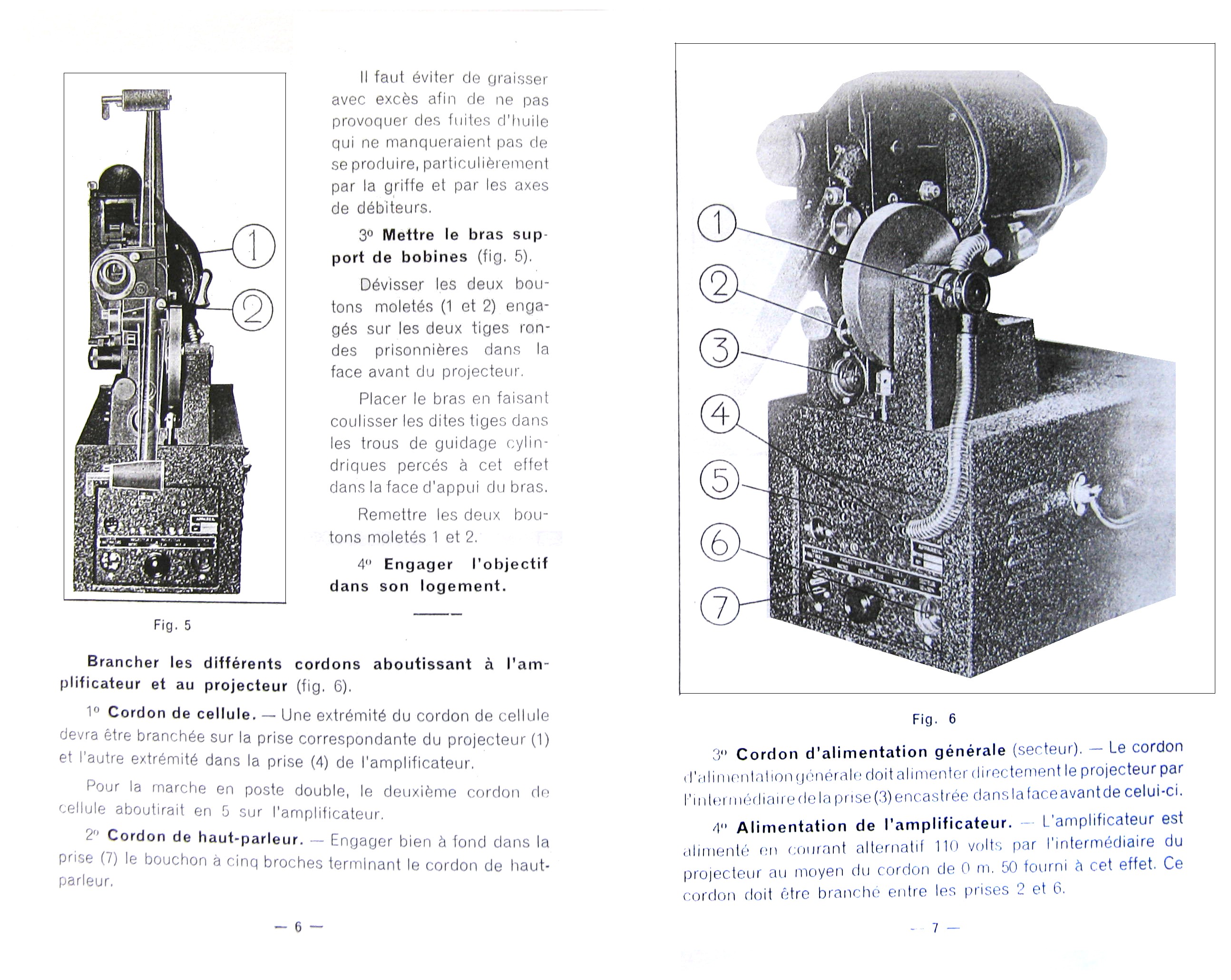
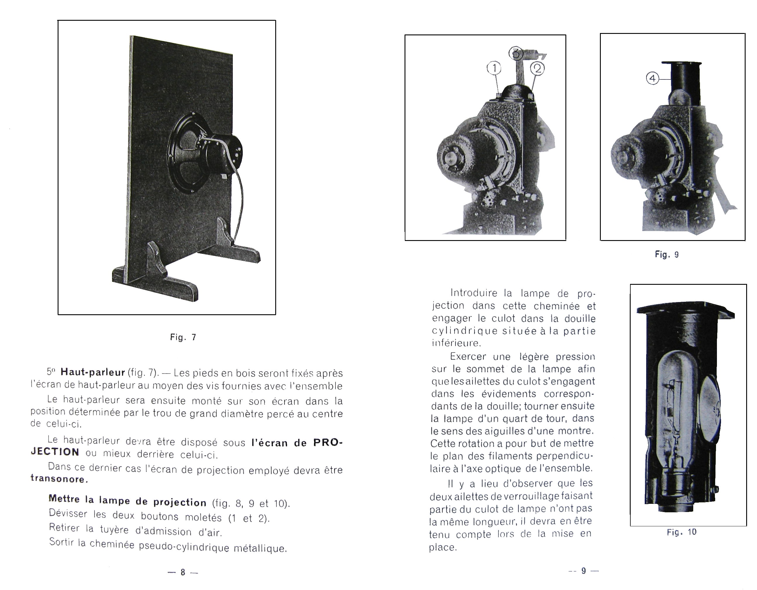
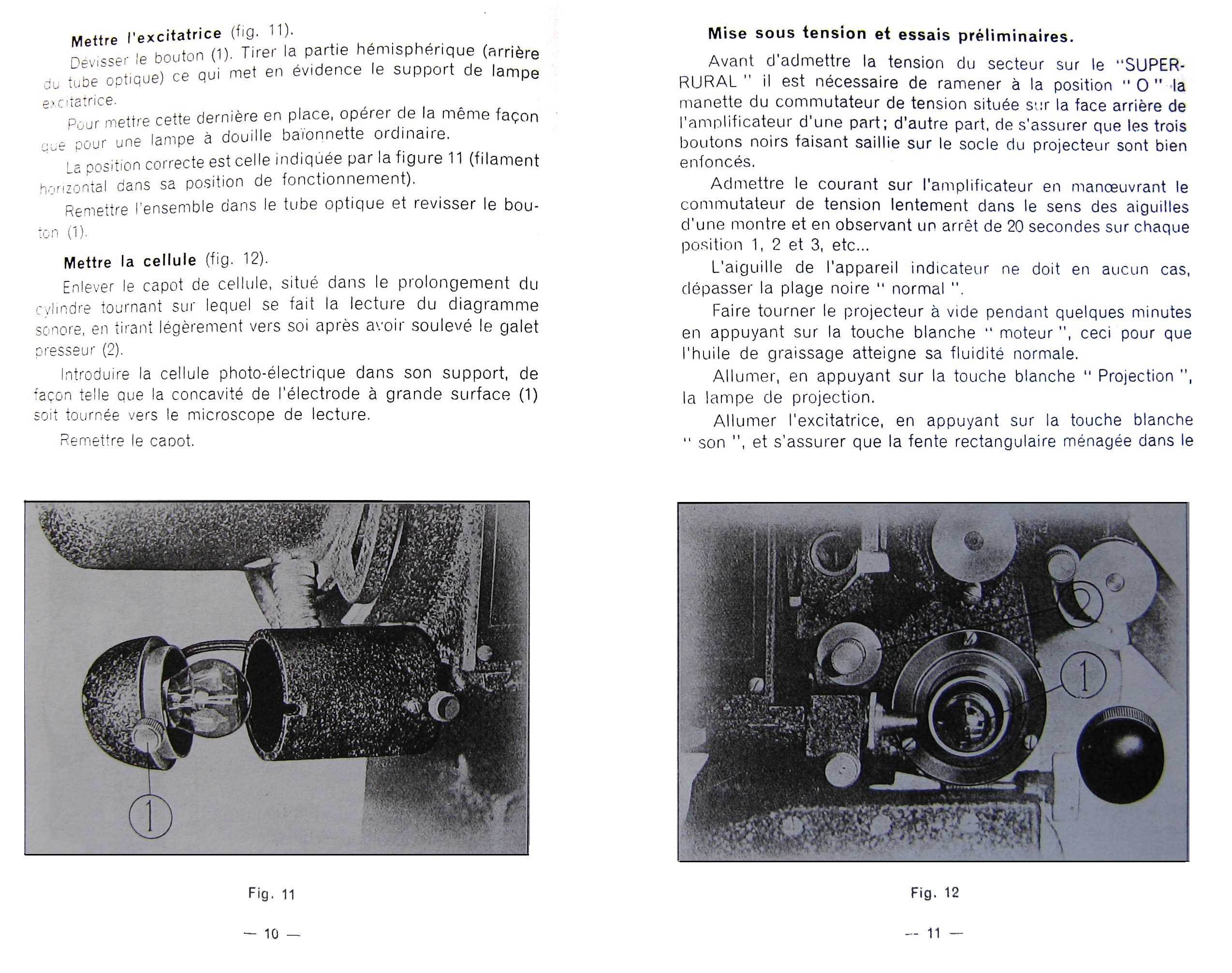
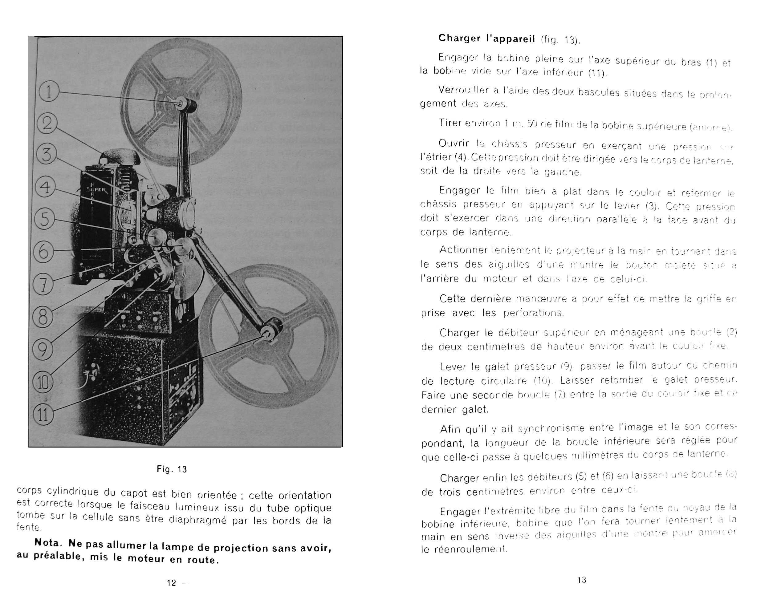
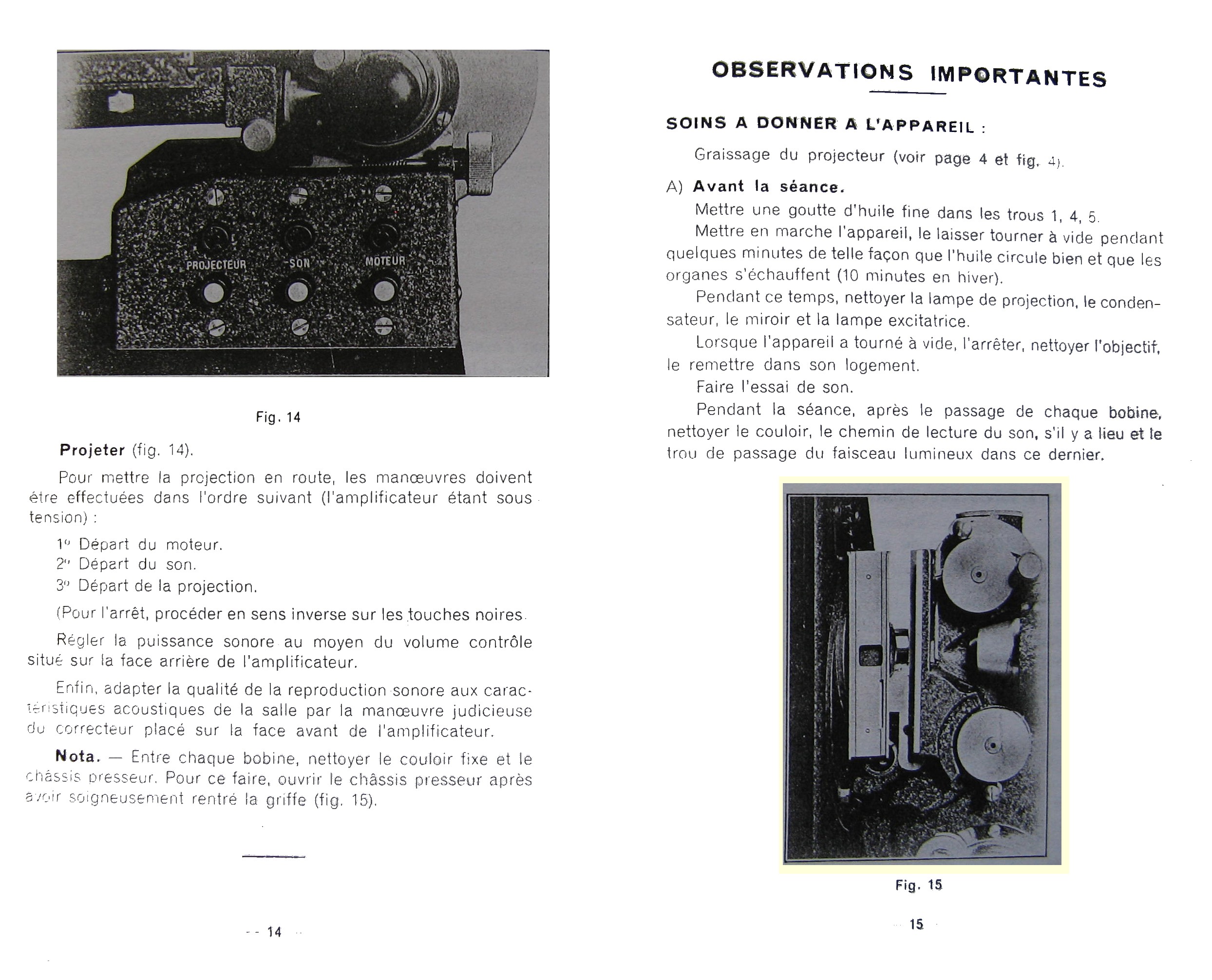
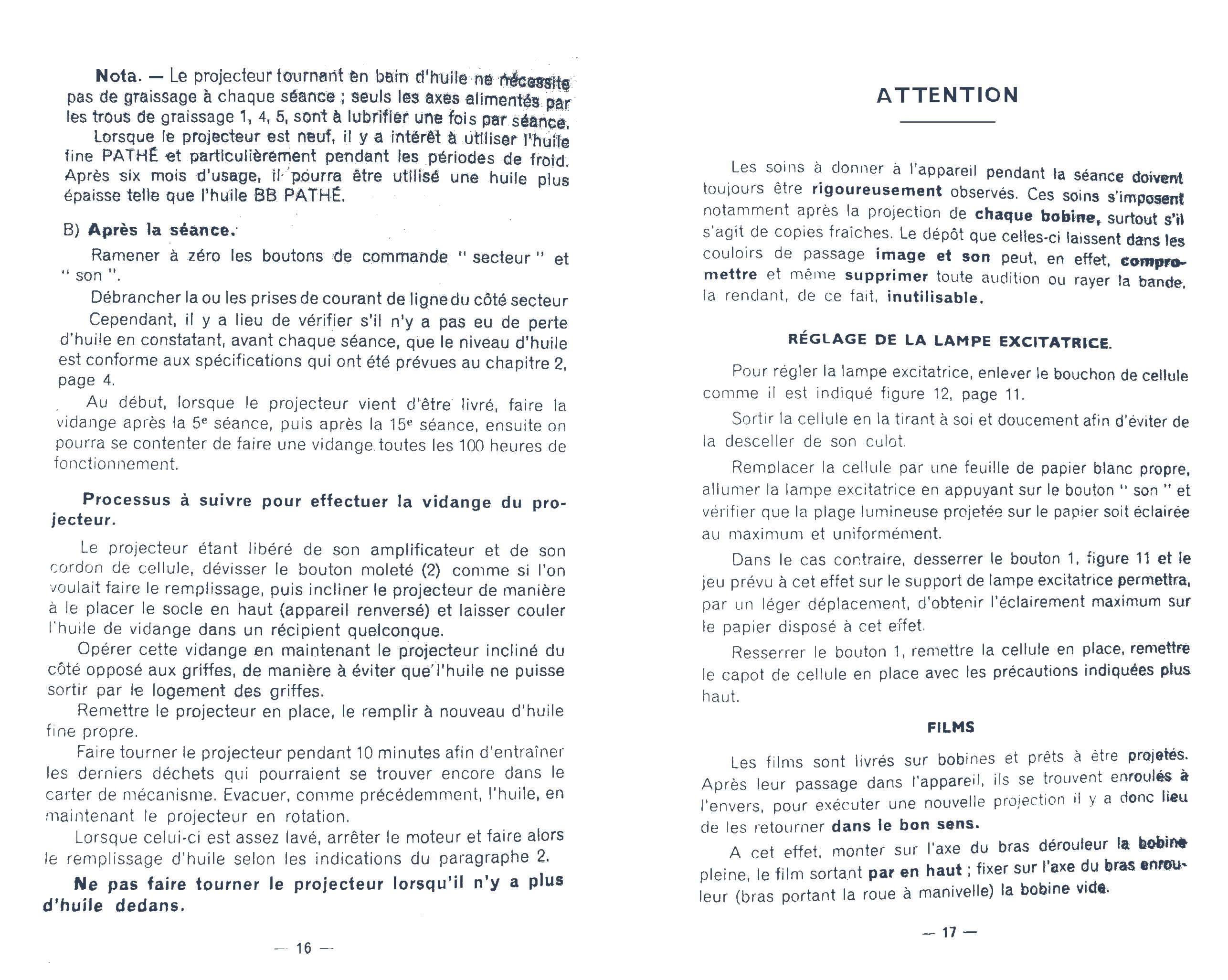
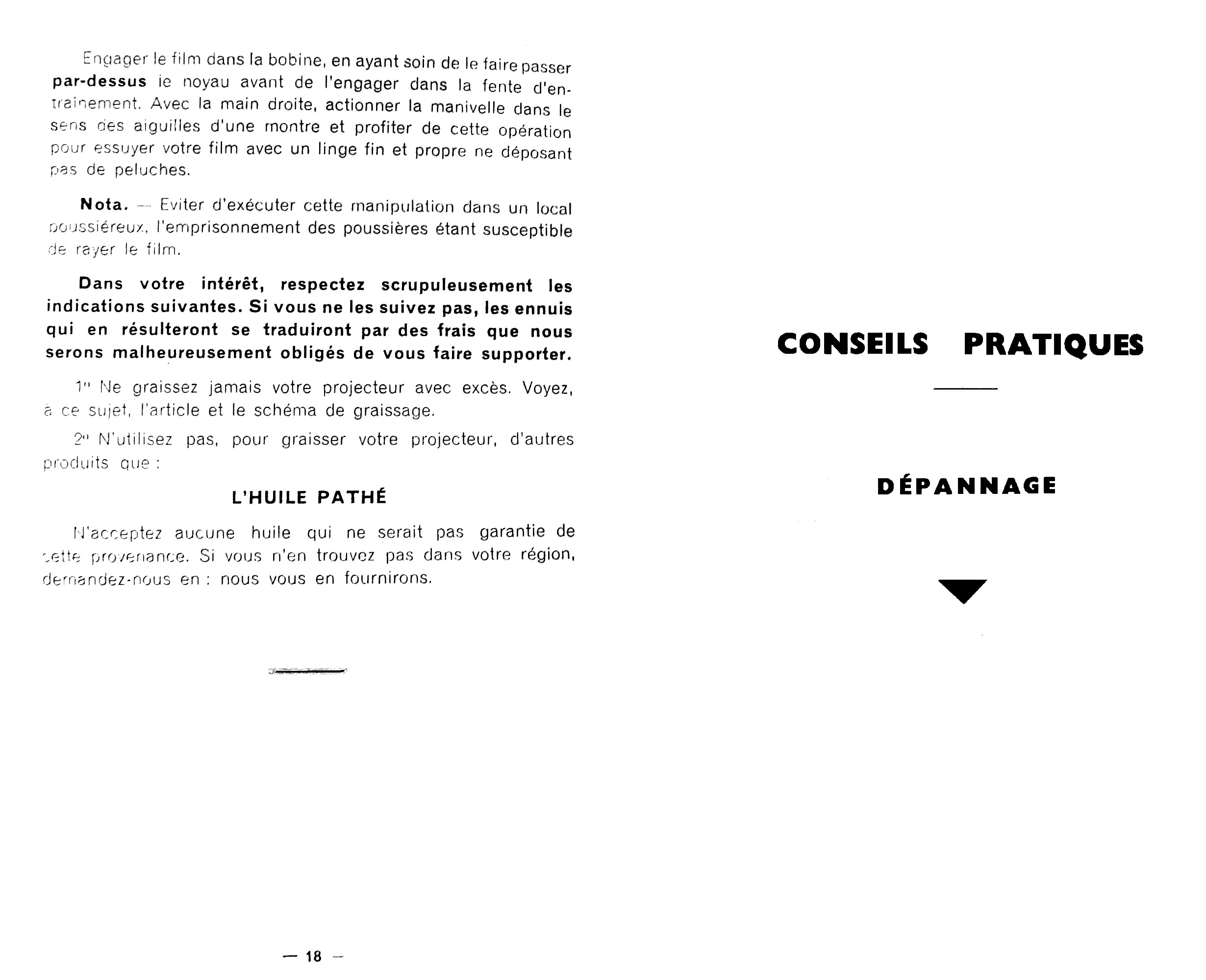
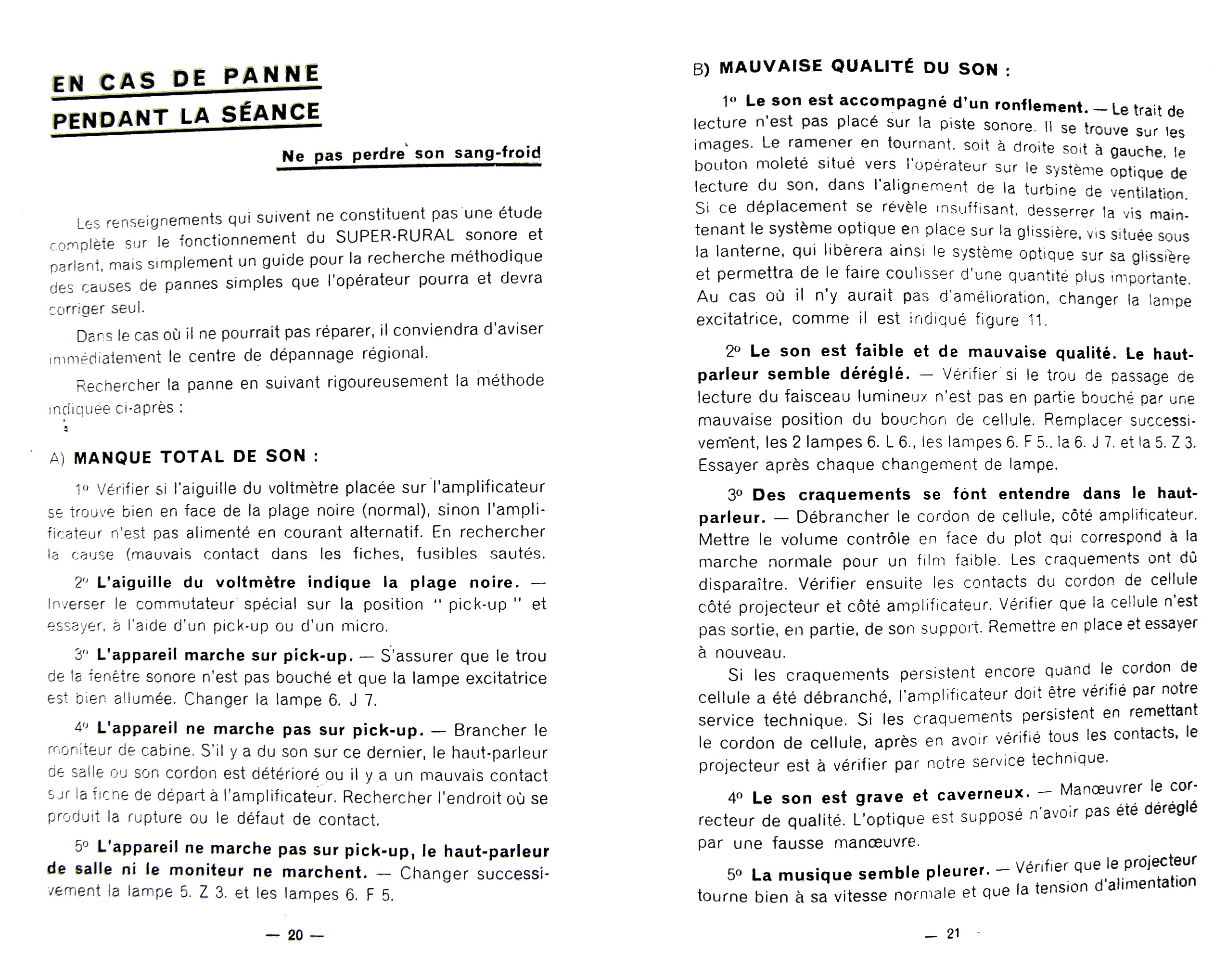
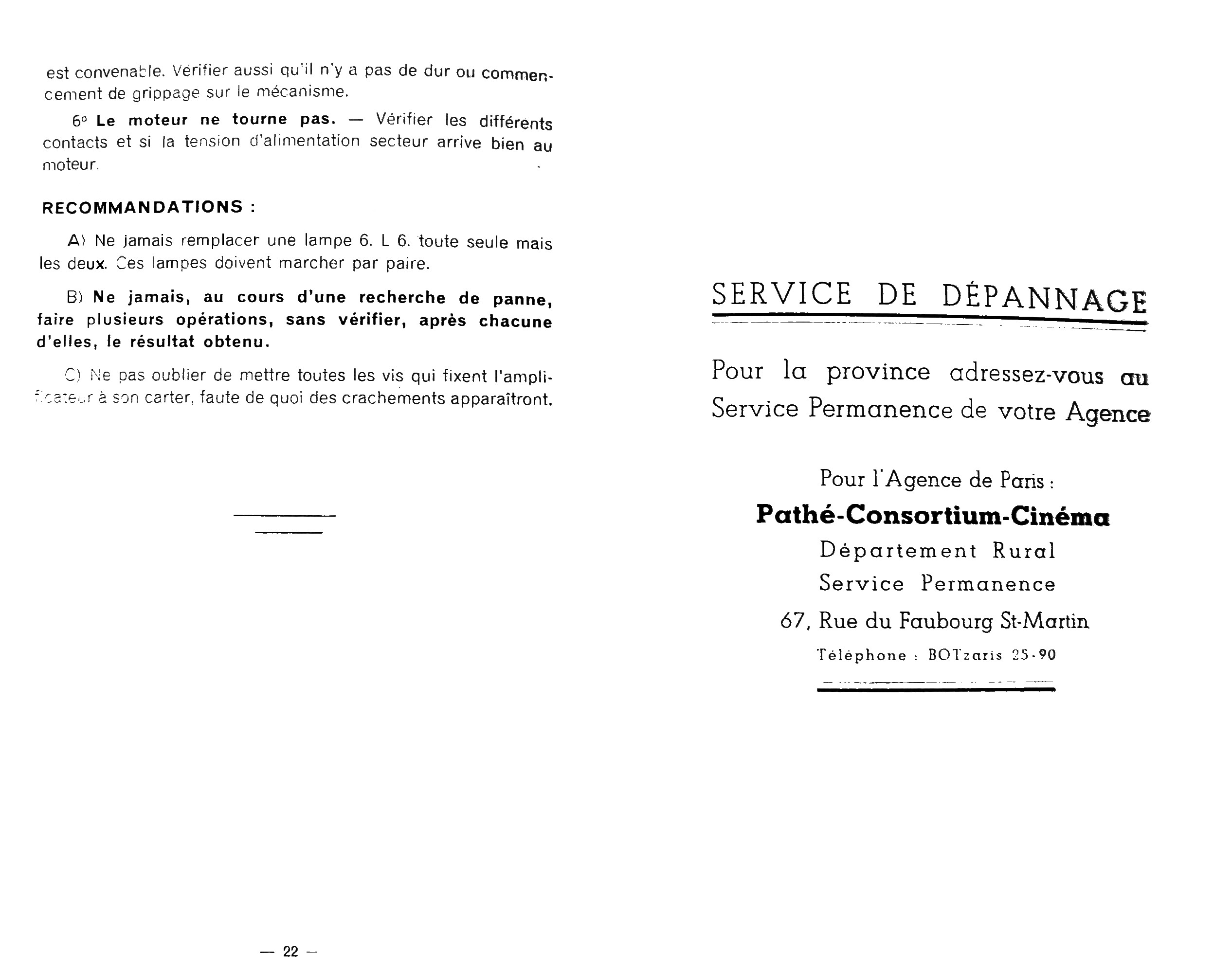
J C Laubie kindly sent me a copy of the instructions for a Super Rural, which are exceedingly rare.

SR 1 SR 3 BB1 BB2 Home Talkie Rural Sonore