Home Talkie
Return to 17.5 Index page
HOME TALKIE AND NATAN 175
I related in Big Brother how I came to acquire a Home Talkie. I now have a couple of v. disreputable Nata 175 mechs so am better able to compare the two.
Here are some pix for differentiation. First, my Ruislip Home Talkie, then two shots of a Natan - the second at least shows a Natan converted to 9.5 as a number were, I gather. More about the differences later.


The first Natan pic shows a photocell arranged for direct reading of the track instead of via a mirror. This I assume was the sort of approach adopted for the fabled (ie I have never come across one) new improved Talkie-in-a-blimp.
I have talked about the few changes I made to my Home Talkie, but the last of these, converting the lamp, was a longer and more complex job. The original lamp is 16v 8 amp, with provision to overrun at 17v and underrun at 8v, for reasons which are not clear to me. I decided to go for 15v 150w. I thought if I left the mains input setting at 250v, this would give about 15v since our mains is now about 230v. As for the increased amperage, I just hope the original transformer was over-engineered. The lampholder is mounted to a rod which fits inside the original lampholder without making any permanent alteration.
The new lamp did however mean some form of cooling would be prudent. I wanted to avoid as far as possible any irreversible changes to the machine, so I made an aluminium ring which is a push fit into the lamphouse in place of the plastic end cap, with a slight lip to stop it going in too far. On this is mounted a 40mm, 12v computer fan from Maplin. It is set to blow rather than to suck as it says on the packet that the fan is good only up to 70 degrees C. I thought the lamp might deliver more than this if the fan sucked. To provide a DC power supply, I had to build a small unit from a kit (Maplin again. Since the demise of Maplin, I have found CPC a useful successor, tho' no local stores, of course) and wire it into the lamp circuit so the fan comes on with the lamp. Power lead goes behind the sound chute and plugs into a socket mounted alongside the lamp and motor connections. (The holes for this and for the lamp switch are the only permanent changes from the original). Future options include a shield to keep the direct airflow away from the lamp (they go black I am told) and another to reduce light spill out through the fan. A higher power lamp (probably fed from an external 24v 250w ex-Elf transformer) is also a possibility, as I find the light is still on the dim side. The power supply for the fan has a variable output so there is some cooling capacity in reserve to cool a brighter lamp.
The original amplifier didn't seem to work and I don't regard them as worth bothering with anyway (times change - I wouldn't say that now [2015 and beyond). So I just took out the valves and fitted a solar cell. This is a bit of a clunky affair, being designed for 35mm and in a big casing, but it does the job and precision in mounting is far less critical. The solar cell mount is screwed to a small metal block with a through hole. The original sound mirror can be unscrewed, leaving a rod which goes into the aforementioned hole in the cell mounting block. The wire is led carefully away and under the motor, but left as a flying lead at this stage. It goes into a pre-amp I built years ago for my Super Vox (which never had an amp at all) and thence to a separate main amp. An integral amp is a longer term project. The alu plate above the sprocket is simply to keep the wire from the cell out of the way.
Even before I had a projector I made myself a 17.5 rewind adapter. I have a 35mm rewinder, Phillips type. The spindle size is the same as both 16mm and 17.5mm (and 28mm for that matter) and the drive to the spool fits into the notch in 16mm spool centres. So it makes a good 16mm rewinder with a 100ft plastic spool as a spacer on the outside, and a 17.5mm rewinder with the adapter (made from an old 16mm camera spool) on the inside. I later made special adapters for my Marguet rewinder.
The machine when I got it was in very good original condition and in its original box with matching speaker (which I passed on to another collector. As with the amp, I have changed my view and would keep it now). There was even the separate gate mask for silent film, and one or two small touches that I had not met before. The mirror was held in place by a bracket, obviously original as it is painted the same colour as the machine, rather than just relying on the friction fit into its ball socket. This is a minor but important point as it is very easy to knock the mirror when threading. The other thing was the provision of two hand rewinders. These are small handles with pins that fit into the holes in the spools around the central spindle. I had previously only seen these for 9.5.
The machine also had all the old problems that I remember, with some pretty fundamental design flaws. First, it has a single sprocket. The amount of contact between the film and the sprocket is therefore very limited. Correct threading is tricky yet absolutely critical. Putting the film through for the take-up easily dislodges it from the feed side. I have seen hundreds of feet of film dented all along the side where it has not been seated on the sprocket pins properly and, of course, many of these dents end up wrecking the sprocket holes. The feed loop is lost and the claw then attacks the perforations.
This leads to the second basic flaw. The feed loop is not only ridiculously short, but the sprocket is offset in relation to the gate (The 9.5 Vox is like this but with a much longer top loop to give a bit of leeway). As far as I can see, there is absolutely no reason why this offset has to exist. It is all the more odd as the film has to come back across again as it goes around the back of the lamphouse, to meet the take-up side of the same sprocket. These two flaws together mean the machine is very unforgiving; there is no slack in the system and the slightest hitch leads to instant damage. The powerful motor has a fair bit of momentum and can run on causing damage over some length of film.
The third flaw is the sound smoothing system. It uses a chute (a similar arrangement was later used on the 9.5 Pax, although the 17.5 one has one side hinged to allow the film to be inserted). There is no additional smoothing between the sound reader and the sprocket. And the wrap around the flywheel is too short. The chute is a particular problem. The instruction book specifies that the film must be pinched together from the sides to take up a bowed profile. With side sprockets this is asking for trouble at the slightest weakness in perforations . Any misalignment of splices is likely to be a problem too. As a bit of a digression, I should mention that the filming from the screen of Lorna Doone hit a new problem, in that the soundtrack "snored" intermittently because the edge of the track was being read. There is no "on the fly" adjustment of the sound track reading as there is on the 9.5mm Vox, although the strip of paxolin that holds the sound chute can be adjusted - but only when the film is not in the way and the screw holding it in place can be accessed. Just because I wanted to, I spent some time developing a way of adjusting the reading of the track during projection.


Here are some pix. I think pic 3 best shows what I did. basically I replaced the paxolin strip and made a screw thread thru the lamphouse (hopefully well out of the way) which enabled movement of the film in relation to the sound telescope. I now think, however, that it might be much easier to maybe spring-load the paxolin strip retaining screw so that the strip is able to move but sufficiently firm to stay in place most of the time.
To return to the plot, the final major flaw of the Home Talkie in my eyes is the lamphouse. Because it is enclosed by the film path, it cannot be enlarged and has minimal cooling from a crude fan on the motor shaft. The same lamp also serves for the sound. Some further comment, relating to the single sprocket and its problems, can be found in Aunt Em, under 17.5 Talkie.
Well, all this lamp fiddling didn't work. With the 15/150, the lamphouse becomes unbearably hot, far too hot in my view to use because of a risk of serious damage. So I tried a 24/150 instead. Rather to my surprise, it worked, tho' light output was obviously well down. Tho' the lamphouse heating problem was less bad, I was also now finding the motor getting much too hot and feared I might cook the wiring. So I tries the front-mounted fan I mentioned earlier somewhere. (Again, all without making any alteration that I cannot reverse.). This cools the motor, but not the lamphouse.


On once more taking up the cudgels to battle with 17.5, I tried a new approach. A piece of 1cm plastic channel can have a fan bolted to one "leg", and the other leg fits rather neatly under the lip of the amplifier cover. I tried this with an 80mm DC fan, then ditto mains, then both, directing air onto the back of the lamphouse. Didn't work.
At this point I started to get the bit between my teeth and decided to have a bit of fun. I got a 120mm mains fan, two "reducers" to drop the aperture to 80 then 60mm, then a piece of semi-flexible 60mm ducting from Halfords. I made two aluminium adapters, one to go in the end of the lamphouse to take the ducting (see below left, looking straight into the lamphouse; the lamp can be seen in the centre), the other to go on the "reducer" and again provide for coupling up the ducting. I tried this first with just one stage of reduction and the 80mm mains fan. Could hardly feel anything coming out of the ducting; most of the air seemed to be going out the wrong way at the back of the fan! Then on to second stage of reduction and the 120mm fan. You can see the total assembly to the right. (Note the mains switch for power to the 80mm mains fan mentioned above which, with the aid of a large washer, fits into an existing vent hole in the amp cover). Finally, this did give me some air, but frankly not a lot and again most of the air coming out of the fan the wrong way. Seemed rather better when I set it to suck rather than blow. At this point, I got a bit discouraged and went away without actually testing, which I suppose I'll have to do. Not very hopeful tho'. (No idea where I'm going to put the fan anyway - no room on top of the projector.) What next? Maybe a hair dryer with the heating element disabled?


This is what I ended up doing in order to test. We in the trade have a technical term for this - we call it "a right lash-up". Two 80mm fans, one mains and controlled by the switch seen in the previous pic, one 12v and wired to come on with the motor, are providing external cooling. The big fan with the ducting is connected separately to the mains and set to blow and held roughly in place by some orange wire; the 80mm DC fan at the front of the machine is disconnected at this stage. With a single reel, there was some evidence that the lamphouse was rather cooler than before, so I was emboldened to try a full 1000ft. This, too, seemed to be OK, but it was noticeable that the motor was starting to heat up quite a bit. Next test is with the big fan set to suck. If this works, I can eliminate the front fan; if not, I shall have to wire it back in.
I have a 17.5 Home Talkie with no end cap for the lamphouse. So I've had to make one. Below are pix of the cap; note shallow recess on outer end and internal baffle to try to reduce light spill. I suppose I could make up a bit to match the vertical section on the original cap, but right now I can't be bothered. The recess referred to will take a paper copy of the original end cap, as improved on the computer and so available in many colours. Sprayed over with clear lacquer this should be reasonably durable.


The reason I was making the end cap was the prospect of a sale. As you know, I always find this painful, but I steeled myself and let my spare (fully working but cosmetically challenged) Home Talkie go. However, this has spurred me on to re-commission another, of which I have most bits save the spool arms, the amplifier cover and, of course, the lamphouse end cap. So I have had to make a second end cap and, this time, I am trying to make the upright bit, too. I will show you this as and when it's finished. I have made the amp cover. Construction is exactly the same as the original, except I have used a filler/glue material instead of spot welding to fix the ends to the main body. I have also left the double holes at the back, rather than opening them out to slots as in the original. This is because I have used thin alu, and I thought it would help to keep it a bit stiffer. Now, of course, it has to be painted, as does the main casting, seen here as sanded down in preparation. I would point out that I am responsible only for one of the extra holes, viz the one for a separate lamp switch alongside the original combined motor/lamp switch. All of the insides of this machine have gone, and the other holes secure a tranny etc. I shall endeavour to make them as unobtrusive as possible, by countersinking the screw heads and painting them black. Although it will be far from original, it will I think be able to show 17.5 quite successfully. I haven't decided about the spool arms yet - one idea I am toying with is using a 16mm long-play device instead, which has its own motor drive for take-up.
I have now painted up the amp cover, plus my now-completed end-cap (made in two parts and fixed together after), the shield tube leading the reflected light of the soundtrack to the photocell (you can see that I chickened out of copying the punched, folded tabs that hold the sound chute on the original and opted for a simple nut and bolt fixing) and the lens-holder.

The Home Talkie lamp reflector mirror had been glued it in place or something; by the time I got all the gunk off, little sivering was left. I looked on the internet and tho' one can do some form of silvering at home, it's complex and needs various stuff - not worth the time, money or effort, wot I do not got anyway. Out of curiosity, I tried spray-painting it with a metallic-look paint but, of course, that didn't work. I have had a mirror re-silvered before, but it cost something like £25, and that was several years ago.
The mirror from a Bolex P8 is a close match - the hole is about 41mm and the P8 mirror is 40mm - and I have in the past hacked about the P8 mirror surround to get a rough fit. Quite a bit of light spill tho' as the P8 surround is not quite right. I just tried making a ring to cover the size difference, but it's very hard working with such a tiny thickness of metal - not a lot of strength in it. I achieved some sort of result, tho' I am not dreadfully happy with it and I am unlikely to do it again unless I can come up with a better idea. Also, the P8 mirror is much thicker than the original, so the plastic back which holds the original in place is no use. I have fudged up a strip of tin across the back to keep the mirror in place for now - I have a friend who has done metal spinning and might be able to help. One has to bear in mind at all times that there is only just room behind the lamphouse to give clearance for the lower loop.
This seems like a good place to stop and take a look at the Natan 175.
The Natan 175
The Natan 175 was the obvious precursor to the Home Talkie, but there are differences. I saw a decrepit example at Argenteuil and noted two differences from the UK model (there may of course be others). First, the mechanism sits lower than on the Home Talkie and on an "island" plinth on top of the lower front part of the amplifier casing, with a gap between this plinth and the rear of the base. On close inspection, the top right picture on page facing P68 in McKee seems to be of this type. The upper picture on P67 (ibid) is the UK type, with the plinth for the mechanism an integral part of the amplifier casing. On the French machine, the connections from motor and lamp to the base are tucked in much more closely under the motor, into its own plinth. Pathescope actually used a picture of the Natan in their advertising for the Home Talkie. It is interesting, if idle, to speculate that the very slow process of getting the Home Talkie out into the market was down to settling the new specification for the revised machine and letting contracts for construction; this might have meant pictures of the Natan 175 had to stand in for a while until the first Home Talkies were available.
The other difference was that the lens housing was mounted with somewhat larger fixings on the French machine. With a little imagination this too can be seen in McKee. What is not seen, however, is that the upper front portion of the lens housing had been notched to form a short "rack" with the fixing knob acting as pinion, as I found when I finally acquired one (albeit only a derelict mech). The effect is to pivot the lens housing around the lower fixing point. My guess is that this was a primitive form of framing or racking, no mechanism for which exists on the UK version. I also had some impression that the French machine was a tad smaller. If so, this might be to accommodate the need for a 240v to 110v transformer for the UK. Oh, and the logo on the plastic end cover for the lamphouse is different.
Here are some pix Ian Green found for me on French ebay, some of which are also used at the start of this Talkie-Natan page. They show the inordinate lengths to which your true cine nerd will go; the first pix are a conversion to 9.5 of a 17.5 Pathé Natan, (tho' I have since learned that similar experiments were done on other machines, including the silent Rural). The last two I'm not too sure what is going on. The last pic may show the way Pathé did the "direct reading" of the sound track that was referred to in adverts for the 1938 blimped Home Talkie - still no sightings of that, tho'.


However, the most important thing for me is that they provide pictorial evidence of the principal differences between the Natan and the UK Home Talkie. Now, whether the Natan was ever sold with just the "island" plinth and not the bigger one, I know not. However, Grahame Newnham told me that the Natan was sold without amplifier, for people to hitch up to their radio's or, I suppose, to the Rural amplifier, which was a separate unit and not integral. What we need is a French, English-speaking 17.5 enthusiast to tell us all about it. The only other difference between the Natan and the Talkie is that the latter has a channel at the base of the combination spool arm, where tha Natan seems to have had a lip on one side only. So, after that brief digression, we can revert to the Talkie in the knowledge that nearly all I have to say will apply equally to the Natan.
Talkie Spool arms
I find that the design phase of a project can take me days of thought and false starts. The question of the missing spool arms for a 17.5 Home Talkie I am refurbishing is a case in point. The drawings you will see below - still only theoretical as work has not started - are the third major design attempt over a period of many weeks. As I have no spool arms and am starting from scratch, I thought I should at the same time make them suitable for 2000' reels - the normal 1000 ft capacity means a reel change every two reels. But the securing/locating pins built into the machine seemed to me a tad lightweight for this job - they are simply studs fixed into only about 0.25 inches of casting. The extra weight and leverage of a full 2000' spool seemed to be asking a lot. So I came up with the idea of using the bolts that hold the two halves of the main mechanism together as extra support. All this, of course, is in pursuit of a solution that makes no permanent alterations to the machine which, as you should know by now, has become one of my main rules.
#


My solution is to add a block to the machine, using the existing pins for location and with one of them extended to use as a fixing just the same as the original. Extra strength comes from a steel plate at the rear. The block is then drilled to take spool arms as per the old style B&H machines, round-ended arms into a hole, but with pins to ensure the arms go in on the correct alignment. You will note the two arms are not in identical alignment; correction for this will be made when I come to the spindles at the other end. I also have to consider how to drive the take-up. Will the existing method suffice, maybe with a double pulley part way up the rear arm to which the existing belt would go, with another belt from there to the end?
Inevitably, some changes have had to be made during the actual manufacturing process. I found that the existing spool arm securing pins were not, as I had hoped, removable, so I couldn't simply insert a longer one as planned. Instead, I made a rod thick enough to take a matching screw thread. (As I ought to have guessed, the thread on the original pins is not a standard one, so required purchase of a special tap and die.) This meant a larger hole through the block, leaving less room for a hole to take the rear spool arm, so I had to reduce that to 9mm. The other significant change to the original design is that I decided to make the rear support plate follow the profile of the bracket block. It may all sound straightforward, but involved many hours of work for me.
My original intention was to take some 12mm square aluminium rod I had to hand, round off one end to an exact fit into the hole in the bracket block and make spool spindles to fit. However, given the amount of work I had already done, I baulked a bit at this. I happened to have a pair of old-style B&H spool arms and, as I intended anyway to use 16mm split spools.. The point about 16mm splits is they can be widened slightly with a washer. I would intend just to have 3 or 4 such spools and to build up films before showing and return them to their normal spools after. Also, the spindle size is actually the same as 17.5 so, with holes for the 17.5 pin to engage into, they can if needed be used on a standard 17.5 spindle, although for my present purpose this isn't an issue. The B&H arms also have a well-proven take-up arrangement that handles 1600 2000 ft reels, something I was a bit dubious about just using a simple belt arrangement as per the Home Talkie.
What I did, therefore, was to make adapters to fit into the B&H arms at one end and the new block at the other, with screw-in knobs as retainers as usual, to avoid any material alteration to the originals. If I had my time over, I would make one or two things a bit different. The adapter for the rear arm would be enlarged to the same diameter as the B&H arm and gently tapered down to the bracket block. This is cosmetic, but more significant is the fact that the internal bores of the B&H arms, never having been intended for use, are I think off-round slightly and also are stepped and tapered. Much closer attention to fitting the adapters more exactly, and more deeply, into theses bores would give a firmer fit. You will see in the last pic I tried two different approaches, a lump on the side to fit into the slot in the B&H arms, and a longer, straight-through securing screw. I think it still needs more work to ensure the whole arrangement cannot twist, eg under the pull of the take-up.
Another thing I found was that with the longer spool arm at the rear, the take-up belt, even when correctly crossed, fouled the flywheel. Fortunately, a simple solution was possible by lengthening the projector thru bolt and adding a couple of Meccano(TM) pulleys. As you can see, I need to shorten the belt a bit - the B&H belt is tight, relying on the arrangement at the end of the arm to provide slack.


The other issue, which I have yet to address in detail, is whether the arms line up with the film path sufficiently well for practical purposes. As you may recall, the hole for the rear arm had to be offset slightly to clear the original mounting pin. I had planned to deal with this simply by where I fixed the new spool spindles I planned to make. We shall see.
The reason I have not yet done a full road test is simply that I want to leave the parts I have newly painted as long as possible to harden before re-fitting everything; this is why in the pix the machine is mounted an a wooden baseboard (it falls over else with those long arms on). There is more yet to do arranging the sound reading, covering various holes in the base and of course painting these new bits wot I have just made, and maybe the B&H arm too. All of this, however, was a bit short-circuited by the acquistion from Ian Green of a completely different and, I have to say, much better design of spool arms for the Talkie.


It is altogether simpler, more rigid and more robust. I guess I just wasn't cut out to be a designer as I do have problems doing spatial visualisation. In fact, this looks much like the work of John Cunningham, who was such a clever engineer I can't feel too much shame.
The mechanism itself also needs work - I don't think it has an oil-tight seal (I think it runs with a small puddle of oil at the bottom, which is picked up by the main gear wheel, which is about 4 diameter, and splashed about the insides generally. I suppose, come to think of it, you'd like some chitterling pix as well while I have it dismantled.
Well, here it is at last, the day you have all awaited for so long - the inside bits of a 17.5 Home Talkie, which I promised you a long time ago.


Dull, isn't it?
I am struck looking at these chitterlings for the first time in many years at the simplicity of the mechanism. There are just two gears, with the single sprocket on the shaft of the large gear and, directly mounted on the motor shaft, a double cam which imparts a completely square motion to the claw, a thing I always thought excellent. I came across one or two twiddly bits which might help someone if they ever fiddle with a Talkie. The sound flywheel can only be removed and, more important, put back, when the two castings are at least partly separated. It may also be impossible to screw in the tiny lens for the sound reader when the flywheel is in place; it may, however, be possible to create enough slack to overcome this by loosening the rear bearing pin. It strikes me that the edge of the sound drum on this particular machine is actually a tad too far away from the sound reader, tho' I have yet to be able to test. This could mean that too much or the wrong part of the track is read, creating nasty noises. It cannot come any closer, because then the larger rear part of the flywheel fouls the projector body. I am considering a little thingy to sit on top of the reader lens, with a small slot in it to limit the width of track read. I am also trying to come up with a way to make it possible to adjust the reading position while the machine is running (as most 9.5 sound machines do). The position can be adjusted, but the retaining screw you need to access is under the sound chute, and you end up with trial and error, and no easy way to cope with varying track positions from reel to reel or, indeed, within a reel which I found with Lorna Doone.
If you look at picture 3, you will see slightly above and to the right of the claw frame two brass-lined holes. These are the two stops in which the pin of the moveable sprocket roller retaining assembly locates (open or closed position). They are clearly later additions, presumably because of wear. I found that the special screw on which this assembly pivots had in a similar manner partially stripped its thread and would no longer grip. The thread was not one for which I have a tap to hand, so as well as making and inserting a threaded brass sleeve, I had to make a new screw as well, so I could use a thread I do have. I've also had to make a screw for the lamphouse pivot, and a replacement roller to replace one of an incorrect design - this assembly and its correct functioning are critical. Fortunately, I have another machine to copy from.
It would appear that the machine is supposed to run with a puddle of oil in the bottom. There is a sight glass; others I have seen require you to keep the oil about half way up the sight glass. It is, however, very difficult to attain a complete seal; the sight glass is especially difficult because, of course, you actually need to be able to see through it afterwards so cannot simply smear it with gunk. That springy arm on the claw frame may be to splash the oil about a bit?
Next are some pics of the sprocket on the Talkie; only the first three are actually a Talkie, the others are a Natan 175 as the eagle-eyed will have spotted.


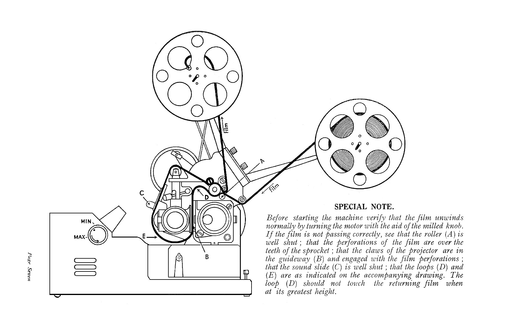
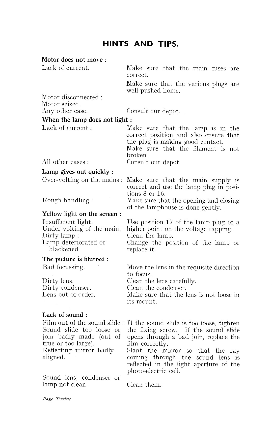
There was the usual good-quality instruction book for the Talkie, which I have scanned in and am gradually cleaning up. This for some reason managed to survive the Great Software Disaster of 2015 so you have to access the pix one at a time. REMEMBER, use the BACK key in the top bar to return to the text before selecting the next picture. First is a pdf to make it easier.
Home Talkie Instructions File.pdf






Here is a magazine review of 17.5, plus a Pathescope Monthjly reference to the fabled "improved" Home Talkie. There are more pix of 17.5 adverts etc in the Publicity section (vis Index page link below).


Return to Index page 17.5